Basic Layout
- Belt has high tension
- One side is tight the other has slack
- Friction is key
Types of Belt Drives
Advantages & Disadvantages
| Traits | Flat | Round | V | Timing |
|---|---|---|---|---|
| Suitable for Long Distance | ✅ | ✅ | ||
| Does not Slip and creep | ✅ | |||
| Minimal noise | ✅ | |||
| Absorbs torsional vibration | ✅ | |||
| High efficiency (98%) | ✅ | |||
| Good for power transmission | ✅ | |||
| Good for precision | ✅ |
Timing Belts
Made of - rubberized fabric and steel wire
Best for - transmitting power at a constant angular velocity ratio
- Suitable for precision applications
V-Belts
Synthetic or steel tensile cords encased in an outer jacket
- Cords - tensile strength and flexing
- Lower rubberized area - withstand compression
- Outer fabric jacket - protection from moisture, heat and dust
V-shape allow tighter wedging - increase friction - higher torque
Multiple belts increase power transmission!
As many as 12 or more can be used on a single sheave
V-belt Standards and Size
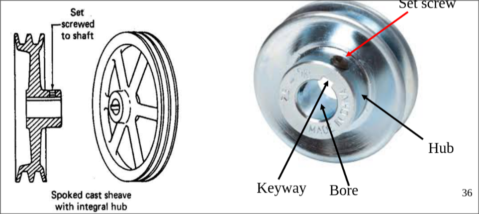
V-belt sheaves with prebored holes
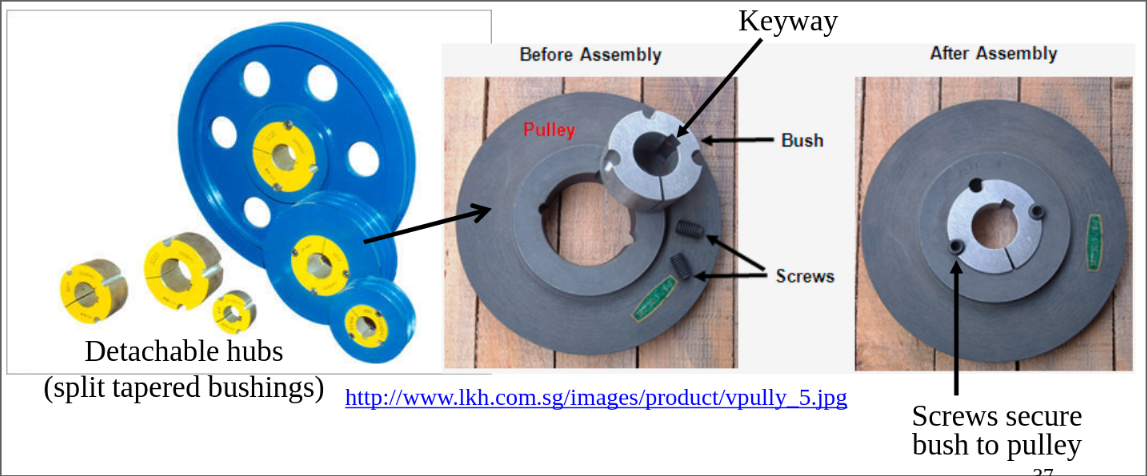
V-belt sheaves with removable hubs
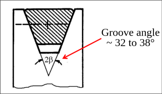
Sheave groove
Its normally 32 - 38°, smaller than the 40° of the belt
- This forces the belt to wedge in tighter
Speed and direction
Speed ratio
Belt speed
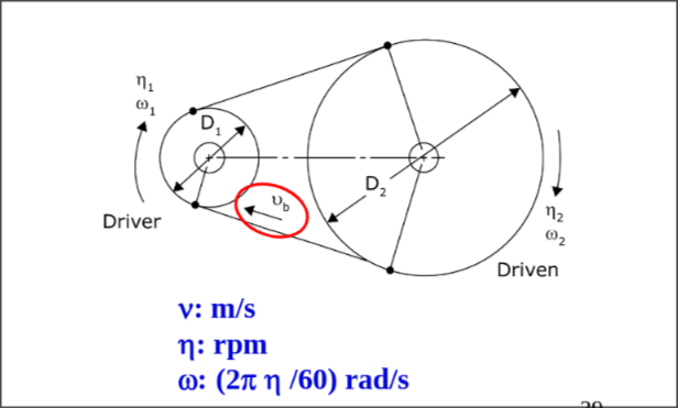
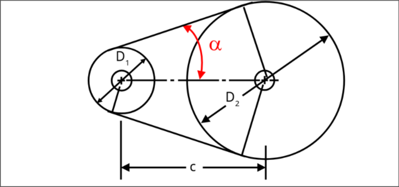
Belt drive geometry
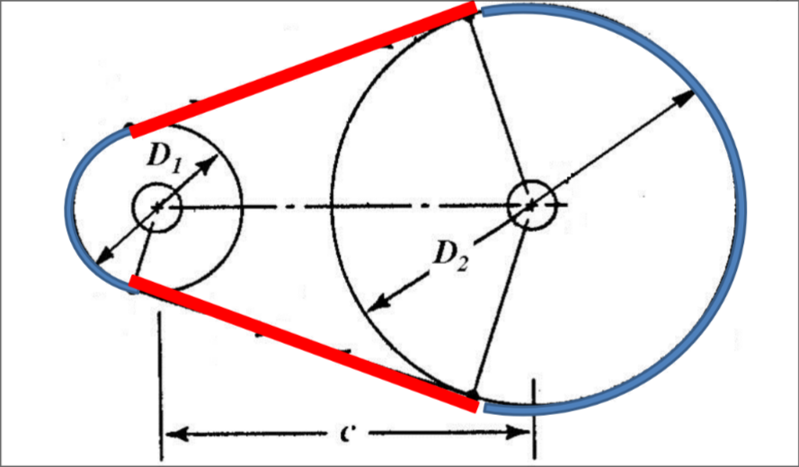
Belt Pitch Length
L = 2 arcs + 2 straight tangent over pitch circles
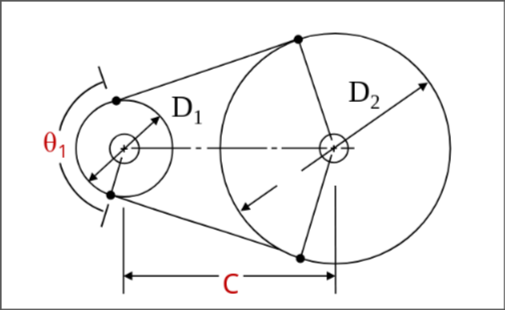
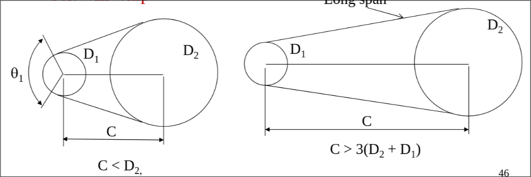
Center distance & Angle of Contact
Center distance:
Angle of contact - on small sheave:
- θ1 should be > 120° to prevent slippage
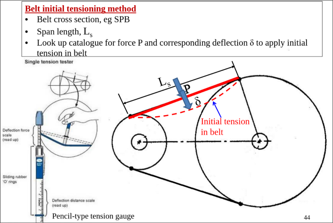
Length of span between sheaves, Ls
- Determines tendency of belt vibration / whipping
Guidelines for Design of Belt Drives
- Belt speed > 33m/s requires special sheaves
- Belt speed < 5m/s consider other drives/gears
- Max speed ratio = 3.0
- Angle of contact on Smaller Pulley > 120° to avoid slipping
- Recommended centre distance:
- to prevent belt slip / whip
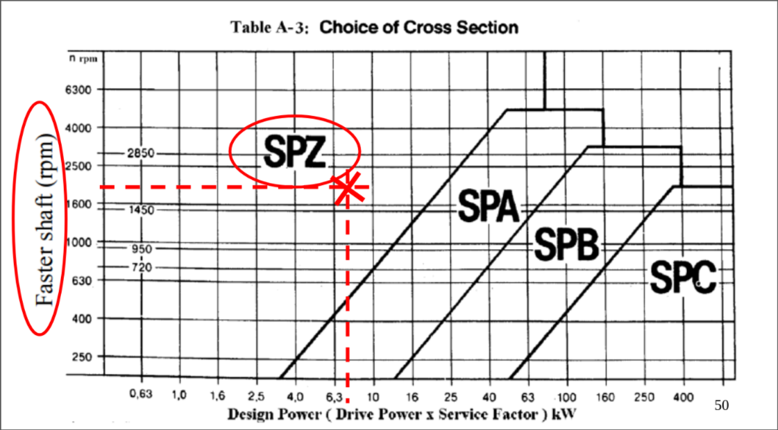
Selection of Belts & Sheaves
- Select minimum belt cross section
- Select standard pulley sizes (pitch diameter)
- Any belt speed between 5 & 33 m/s is ideal
- Specify belt pitch length
- Determine the number of belts required
Design power - to select minimum belt cross section
Service factor - from Table A-2 (Appendix A) Actual drive power - power requirement of driven machine
Corrected Rated Power
The actual configuration of the belt drive can be different from that used by the manufacturer to test the belt for its rated power. The manufacturer used the same diameter for the driving and driven pulleys, and a certain belt length.
- Rated power - standard value from manufacturer power rating tabler
- Cθ & CL - from table A-5 & A-6
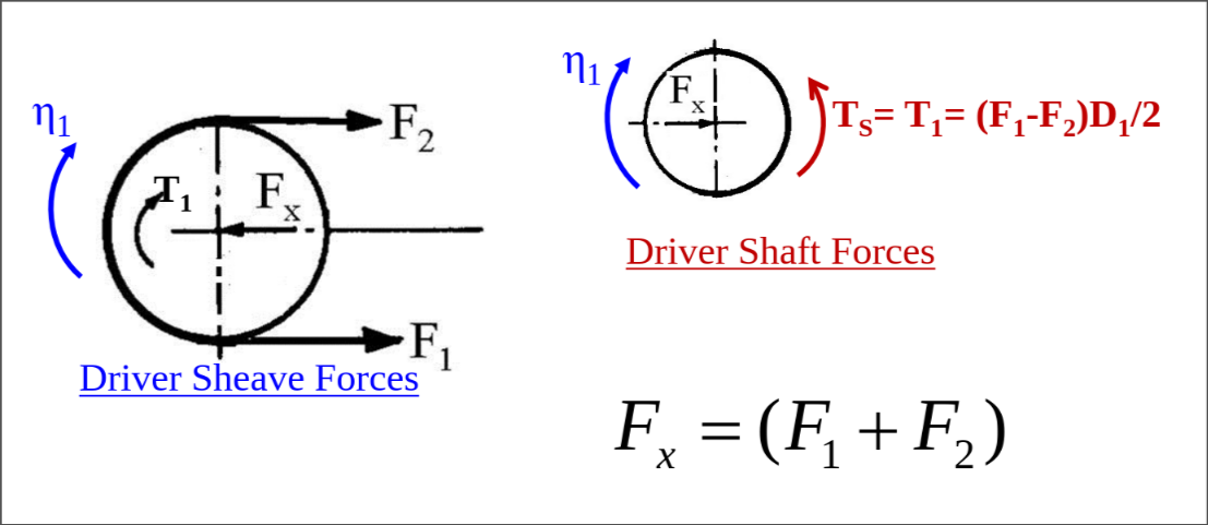
FBD of belt drive
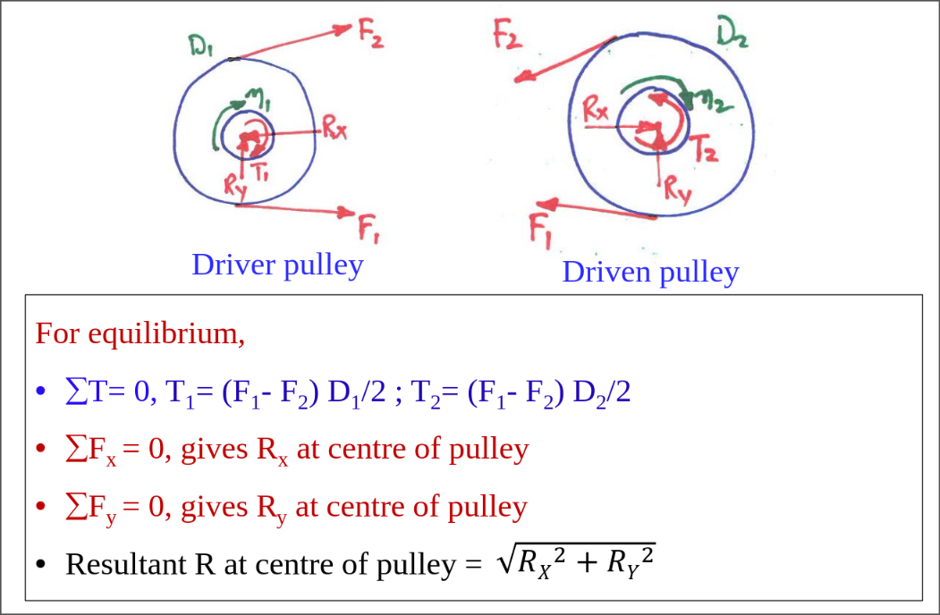
For typical applications, the tight and slack tensions F1 and F2 are assumed to be parallel:
References
Return to MA3001 Machine Element Design - Home