Intro to manufacturing
Are these manufacturing processes? → Manufacturing is about shaping
-
Assembly ❌
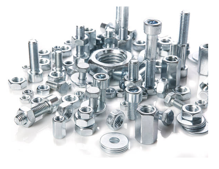
Fastening
-
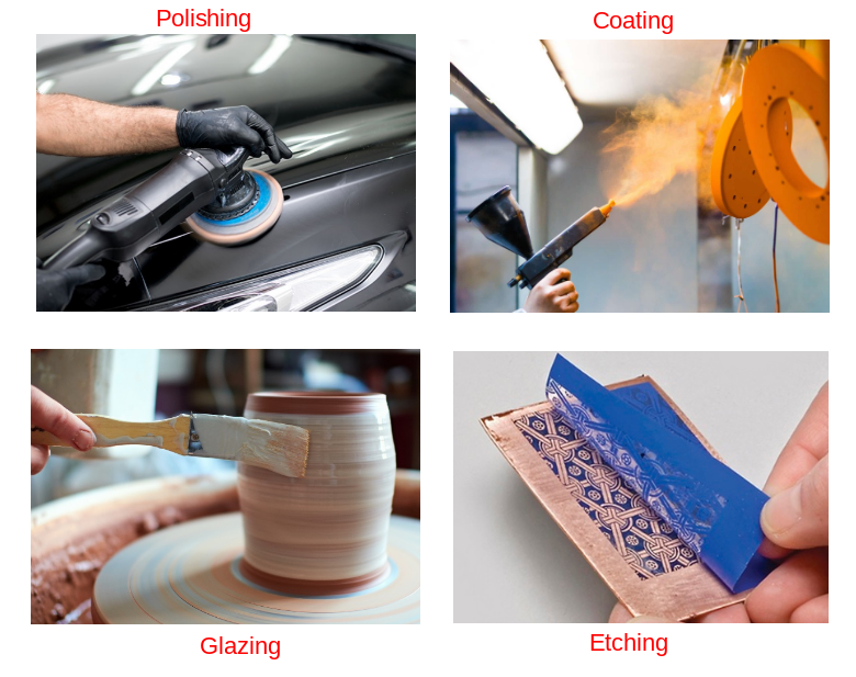
Surface finishing ❌
Polishing, Glazing, Coating, Etching
-
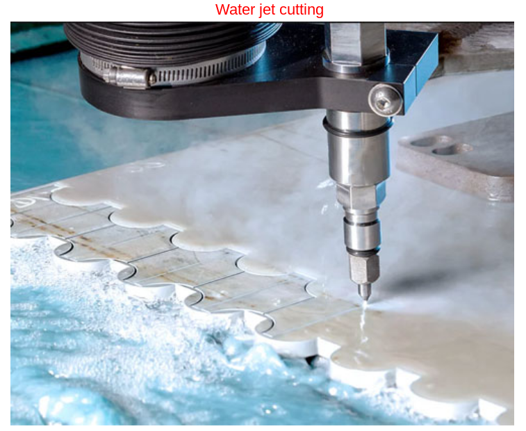
Subtractive processes → weight drop
Cutting
-
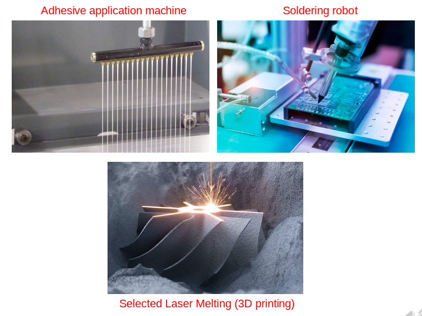
Additive processes → weight gain
Gluing, soldering, 3D printing
-
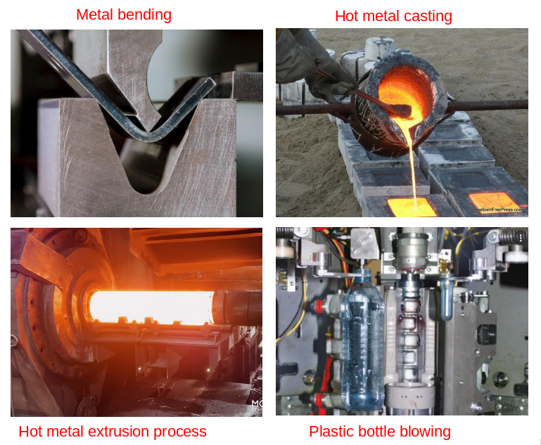
Formative processes → no change
Bending, Casting, Extrusion, Blowing
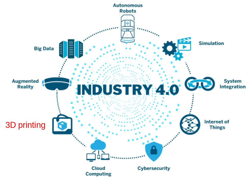
Trending in manufacturing
-
Micro and nano fabrication
- properties are different due to scale
- sensitive to environment → require clean room
- E.g. microelectronic wafers
-
Robotic-assisted fabrication
- needed to satisfy demands
-
Green manufacturing
- considers pollution
- aims to be sustainable
Precision & Accuracy
Precision = repeatability Accuracy = close to true value
-
Precision in Manufacturing
Precision of machine tools is their degree of repeatability for performing an action the same way each time, without generating random error, referred to as ‘quality’
-
Accuracy in Manufacturing
Accuracy of machine tools is their degree of conformance to a known standard or value, without generating systematic error.
Dimension and Tolerance
Tolerance - the allowable deviation from the value that we can tolerate for a part
- +0.005 and -0.005 means tolerance = 0.01
Measuring instruments
-
Measuring length
Calipers and micrometer
-
Measuring angles
Bevel protractor, Sine bars
-
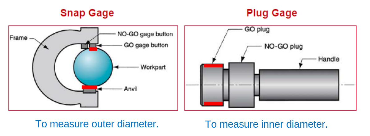
Fixed gauges
OR GO/NO-GO gages
- GO limit: used to check the dimension at its maximum material condition
- No-GO limit: used to inspect the minimum material condition of the dimension in question
Surface finishing and Measurement
-
Surface texture are repetitive or random deviations from the nominal surface of an object
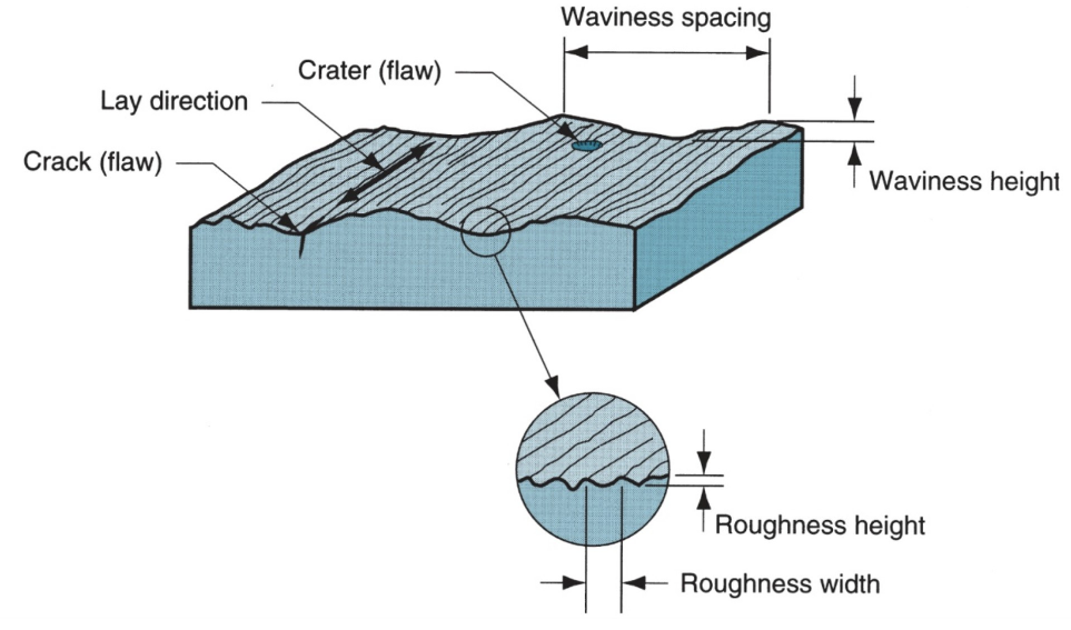
Roughness ~ lack of precision: small variation around nominal value Waviness ~ lack of accuracy: large variation around value
-
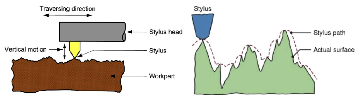
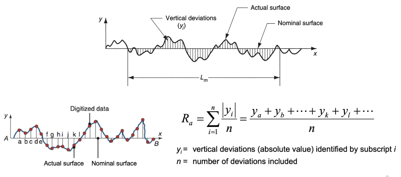
Measurement of surface can be done with a stylus instrument
Calculation:
Polymer Engineering
Fundamentals of polymers
-
A polymer is a large molecule (high molecular weight) constructed from many smaller structural repetitive units (monomers), covalently bonded together (crosslinks along the single polymer chain)
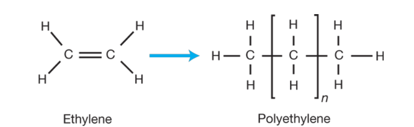
Polymerization: Monomers are activated and react with each other creating chains
-
The reaction is hard to control
-
Molecules bind to closest neighbours
-
Molecules formed are massive and can be poly-dispersed Plastics = Polymers with Additives
-
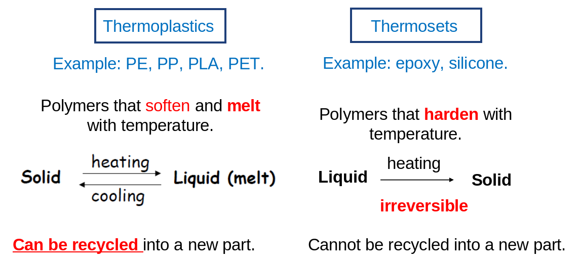
Two big families of polymers → Thermoplastics & Thermosets
-
Thermosets have crosslinks that do not break with heating
Two key types are listed below
-
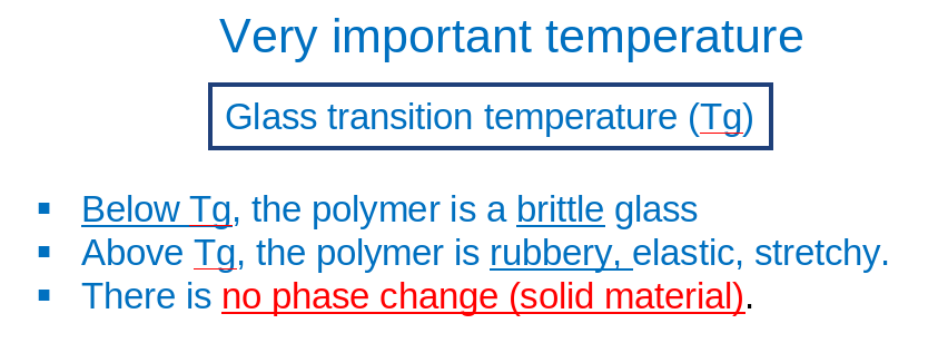
Thermoplastics molecules slide when heated above glass transition temperature (reptation)
Properties of polymer melt
- Viscosity is the resistance to flow
- The viscosity of a polymer melt decreases with shear rate, and therefore becomes more fluid at higher shear rate. This is called shear-thinning or pseudoplastic fluid behavior
- Viscosity also decreases with temperature
- Shear history also decreases viscosity
- Viscoelasticity: Delayed reaction to stress
Polymer forming process
Processes are applied during soft, liquid form Casting - Extrusion - Injection Molding - Compression Molding - Transfer Molding - Blow Molding - Thermoforming
Casting
- Pour liquid polymer into mold, using gravity
- Simple molds only
- Low production quantity as it is manual
- Can be used for encapsulation (electronics)
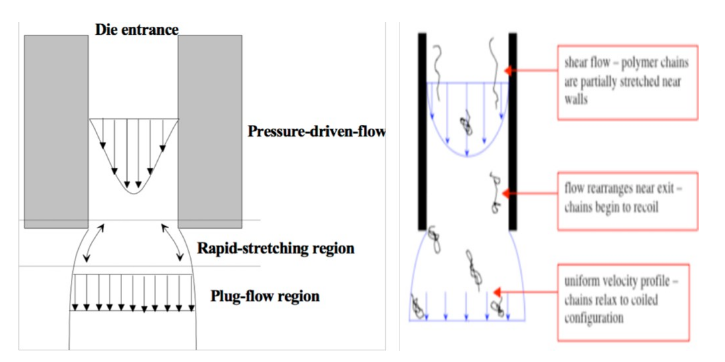
Extrusion
Extrusion is a continuous process for making profile shapes (rods, fibres, tubes, etc.), films and sheets or parison (the preform for blow molding)
-
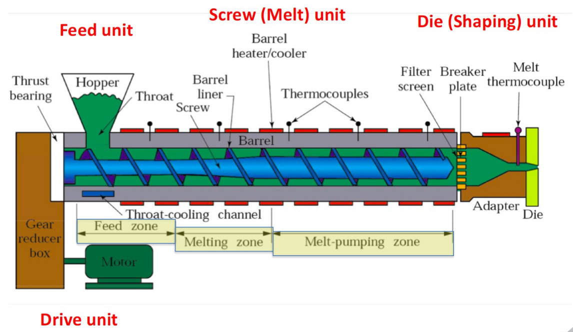
Single-Screw extruder
-
Shear Heating is the main mechanism for melting the polymer Process flow: Polymer pellet feeding → Screw convey pellet into heating zone → Friction + Heaters melt pellet → Liquid polymer pass through die → Desired shape extruded Process Zones:
-
Feed zone: Constant screw depth - to preheat and convey to next zone
-
Compression zone: Decreasing screw depth - To squeeze trapped air back to feed zone - Improving heat transfer
-
Metering zone: Constant screw depth - Homogenized melting here to provide constant melted polymer
-
Filter & Breaker plates: Straighten the spiralling flow - Create back pressure, better mixing Extrusion defects:
-
Die swell
- At a fixed shear rate, increasing die length decreases die swell.
- Die swell from a slit is generally larger than from a capillary.
- It is important to design the correct exit shape to obtain the desired product.
-
Shark Skin & Melt Fracture
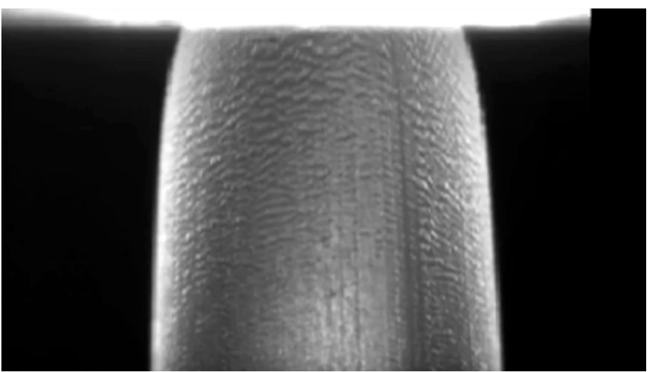
- The distortion of the extrudate is induced by high shear stresses at the walls
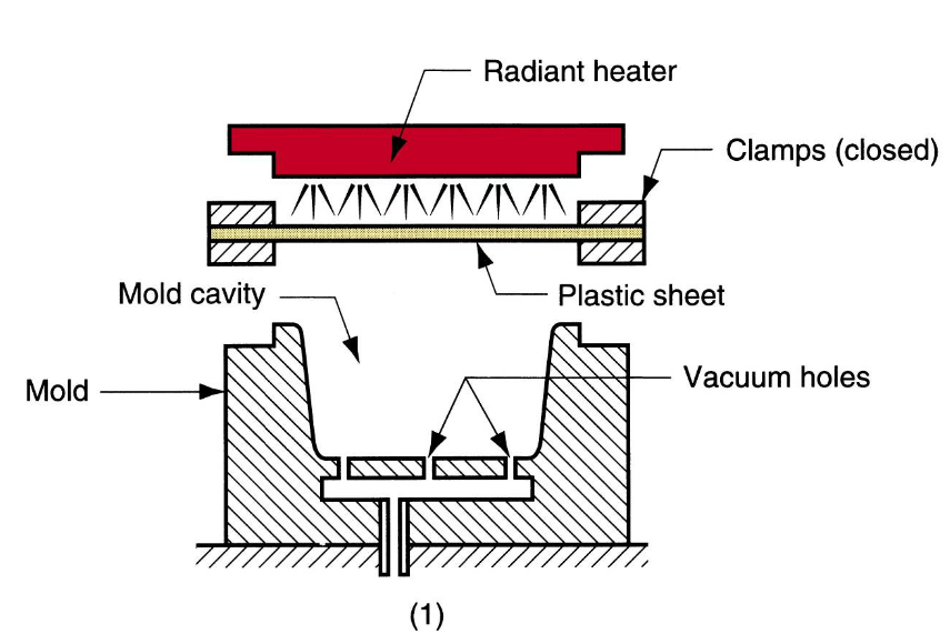
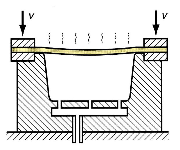
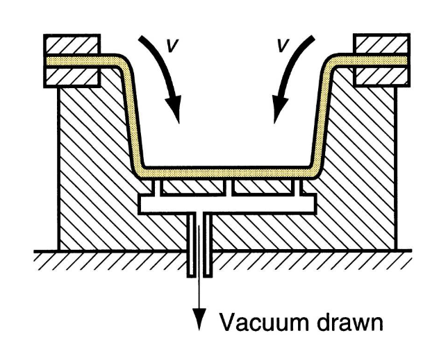
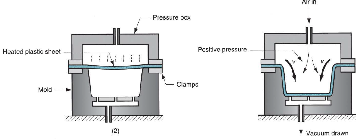
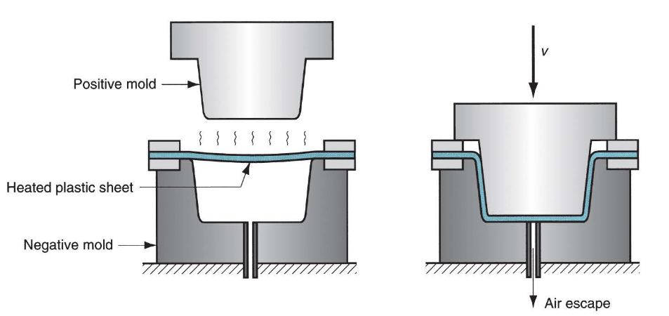
Thermoforming
Flat thermoplastic sheet heated and deformed into desired shape using a mold
Vacuum thermoforming:
-
Flat plastic sheet is softened by heating
-
Softened sheet placed over concave cavity
-
Vacuum draws sheet into cavity
-
Pressure thermoforming: Higher pressure can be used
-
Mechanical thermoforming: Better dimensional control and surface detail but higher cost
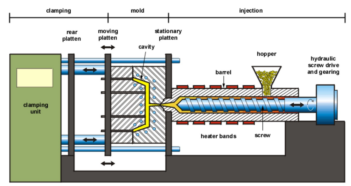
Injection molding
Polymer is heated to a highly plastic state and forced to flow under high pressure into mold cavity to solidify
-
Almost always net shape
-
10 - 30s cycle time
-
Multiple cavity for multiple parts
-
Only economical for large quantity due to high mold cost
-
Complex and intricate shapes possible
-
Limitation:
- Mold must but makable
- part removal must be possible
-
The equipment
-
Pressure history
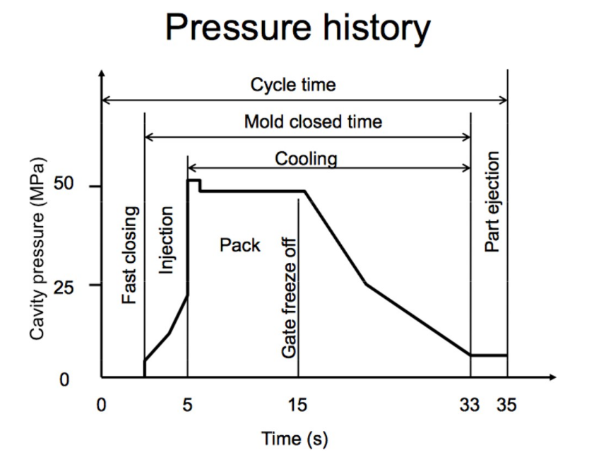
Process: Mold is closed → Polymer melt injected → Screw is retracted → Mold open and part ejected
-
Ideal Runner Shape
-
Ideal Runner Flow
-
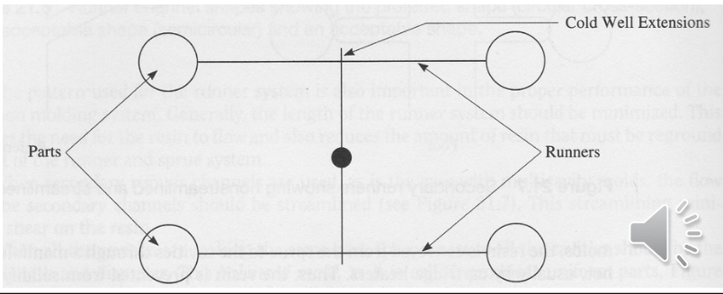
Cold Well Extensions
Dimension of mold cavity must be bigger to account for shrinkage
 Factors affecting shrinkage:
-
Injection pressure
Higher pressure → reduce shrinkage
-
Molding temperature
Higher temp → lower viscosity → more packing → lower shrinkage
-
Compaction time
Longer → more material in → less shrink
-
Thicker part = Higher shrinkage Type of Molds:
-
Two-plate Mold
- Ejector pins push the mold out of the cavity
- Cool water cooling system cools the plastic
- Air vent in the mold allow air to escape while the polymer melt enters
-
Three-plate Mold
Advantages over the 2-plate mold:
- As the mold opens, the runner and the parts disconnect and drop into two containers under the mold.
- It allows automatic operation of the molding machine
-
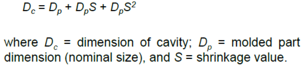
Hot-runner Mold
- keeps runner channels heated and liquid, ready to inject into the cavity in the next cycle
- Advantage: saves material Injection Molding Defects:
-
Short shot: incomplete mold filling
-
Flash: Leak due to too much material injected
-
Sink marks and voids: Too thick sections → Insufficient material to compensate shrinkage
-
Weld lines: Polymer flow meets in opposite directions
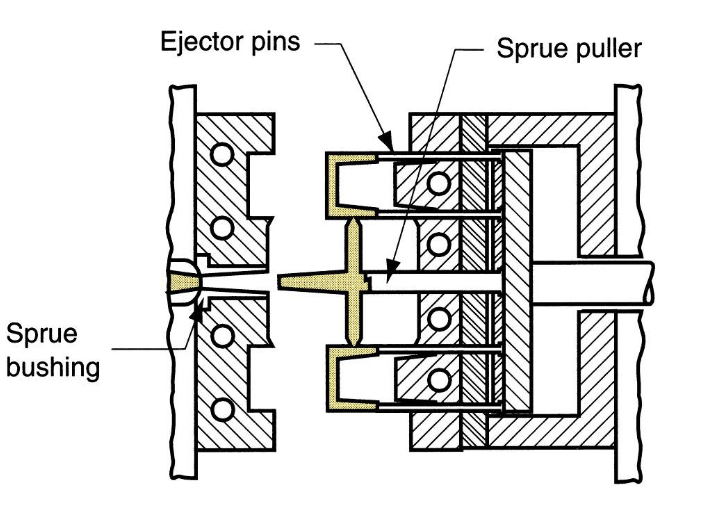
Compression Molding
-
Process: Granules loaded → Pressed and melted → part cool and open
Mold is simpler than injection molding, no sprue and runner Limited to simple part geometry Mold must be heated (electric resistance, steam, hot oil circulation)
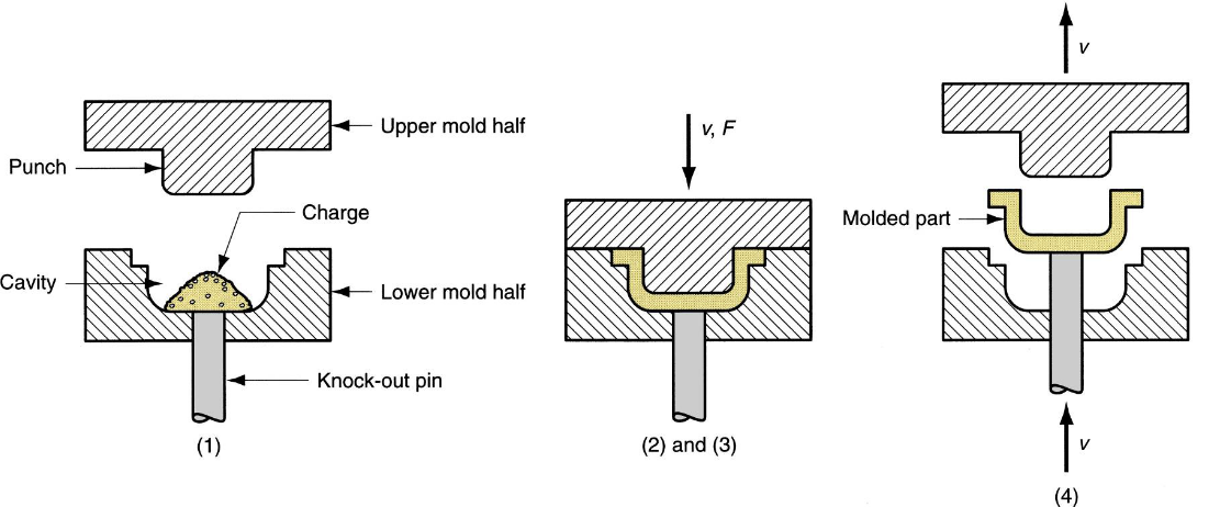
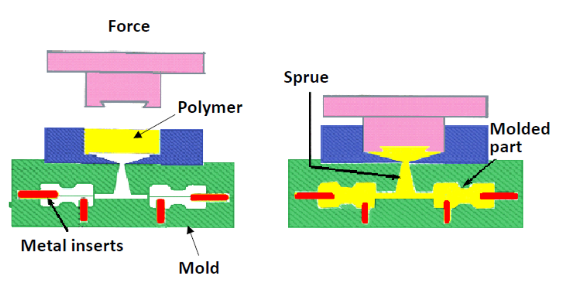
Transfer molding
Modified from Compression Molding: Liquid instead of granules
Process for Thermosets: Charge loaded at mold entrance → Heating → Pressure applied to force into mold → curing
-
Pot transfer molding process:
-
Plunger transfer molding process:
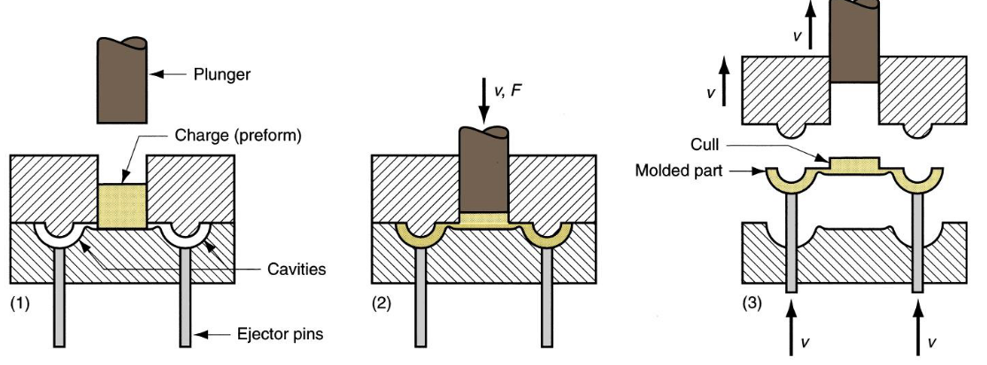
Compression vs Transfer molding:
-
In both, scrap is produced (Cull)
-
Intricacy: Injection > Transfer > Compression
-
Transfer is good for molding with inserts (IC chip)
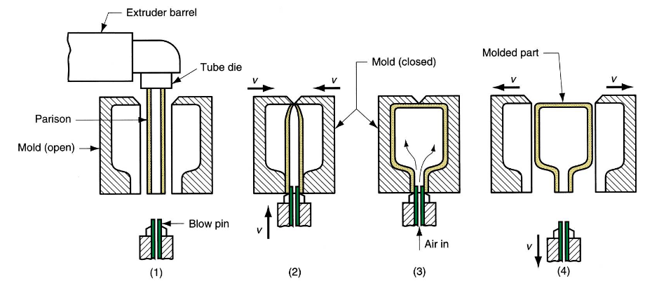
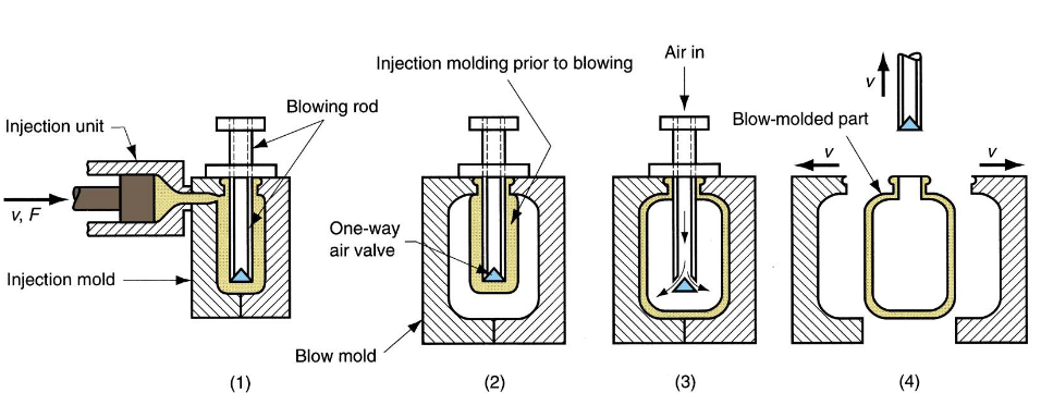
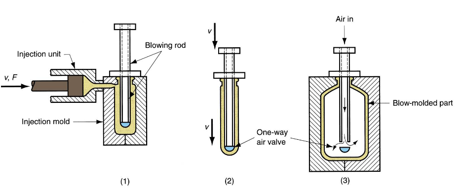
Blow molding
Air pressure inflate soft heated plastic into mold cavity (thermoplastics only)
Fabrication of starting tube (parison) → inflation to desired shape Parison is created via other means (injection molding, extrusion)
-
Extrusion blow molding
-
Injection blow molding
-
Stretch Blow molding
-
Variation of injection blow molding where blowing rod stretches the soft parison for more favorable stressing
-
More rigid, transparent and impact resistant structure achieved (Mainly used in PET)
-
Metal forming
Bulk Deformation Process
Rolling - Forging - Extrusion - Wire and Bar drawing
To induce shape change on workpiece using plastic deformation via force application
Merits:
- Produces common shapes inexpensively
- Can achieve significant shape changes in the workpiece while maintaining good mechanical properties
- Produces little or no waste byproduct
- Achieves final product geometry with minimal or no post-machining required
Hot/Cold Rolling
Important
Thickness of workpiece is reduced by compressive force exerted by two opposing rolls
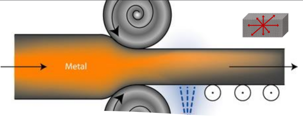
Hot rolling:
- 850–1200°C for steel
- When massive deformation required
- End product = No residual stress + isotropic properties
- Limitations:
- difficult to achieve close tolerances
- surface exhibit oxide scale Cold rolling:
- 60 - 180°C
- Less severe deformation required
- Mechanical properties improved
- Strength increased through strain hardening
- Good finishing
Sheet Metalworking Process
Shearing (blank/punch) - Bending - Drawing - Others (stretching)
To manipulate sheets of metal formed in the Rolling and Cutting process into various shapes via Bending and Forming processes
Merits:
- High strength
- Good dimensional accuracy
- Good surface finish
- Relatively low cost
- Economical mass production for large quantities
Shearing (Blank/Punch)
Important
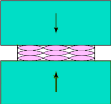
Using punch and die, sheet metal is cut by subjecting it to shear stresses between two sharp cutting edges
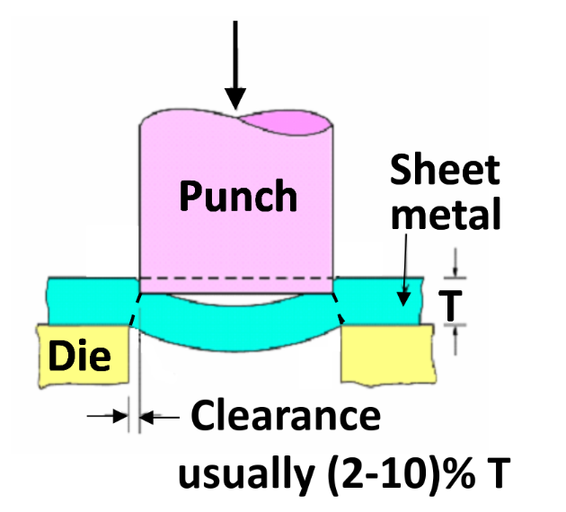
Features of sheared edges
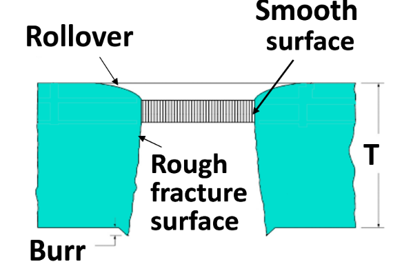 Effects of clearance
-
Sheet pulled into clearance rather than sheared
-
Burr height
-
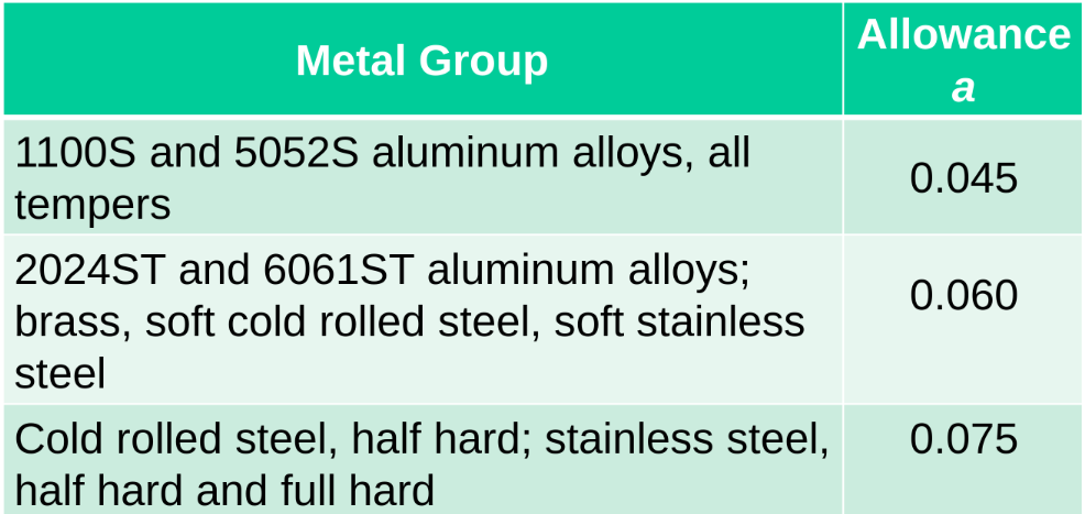
Punch force , wear on dies Recommended clearances where c = clearance, a = allowance, t = sheet thickness
 Blanking vs Punching
Blank → part is sheared out
For round blank of diameter D
Blanking vs Punching
Blank → part is sheared out
For round blank of diameter D -
Punch diameter = D - 2c
-
Die diameter = D Punch → hole is sheared from part For round hole of diameter D
-
Punch diameter = D
-
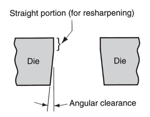
Die diameter = D + 2c Angular Clearance
-
To allow slug / blank to drop through the die
-
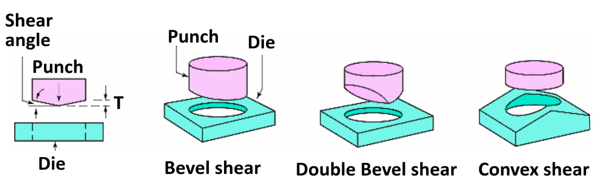
~ 0.25to 1.5 on each side Max punching/blanking force or S = shear strength (MPa) T = sheet metal thickness (mm) L = total length sheared (mm) UTS = ultimate tensile strength Bevel shear and die
 Cutting force
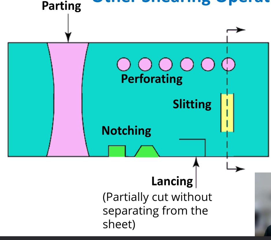
Other Shearing
Shaving
- removing extra material from a rough sheared edge to give a good surface finish
- Very small clearance between punch and die
Fine Blanking
- smooth & square edge
- good dimensional tolerance
Others
Bending
Bend allowance
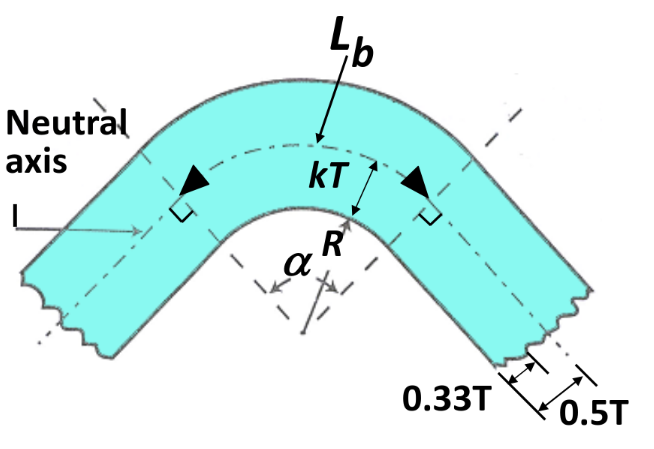 Recommended values for k:
R < 2T, k = 0.33
R ≥ 2T, k = 0.5
Minimum bend radius
Recommended values for k:
R < 2T, k = 0.33
R ≥ 2T, k = 0.5
Minimum bend radius
Bend radius R which a crack appears
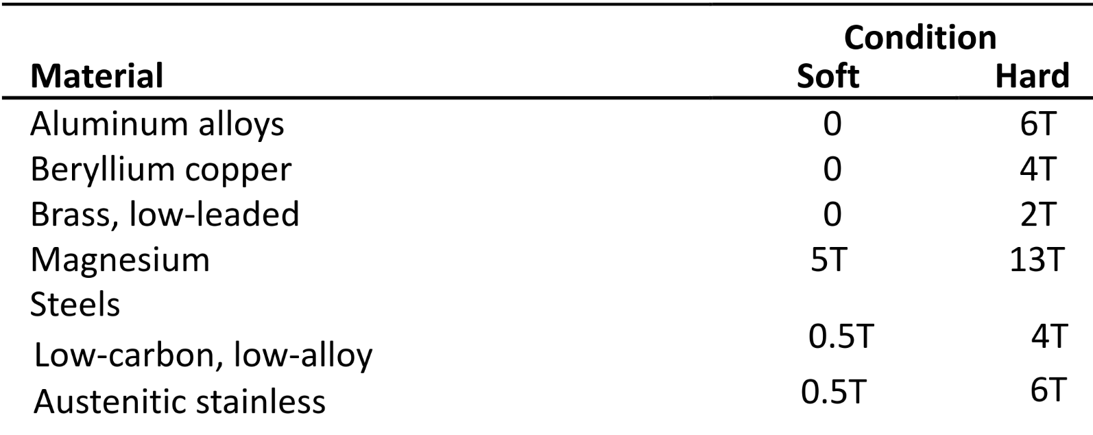 Anisotropy of sheet metal - exhibiting different behaviour in different directions
- Preferred grain orientation
-
Compressing isotropic metal via rolling aligns grain boundaries along horizontal direction
-
- Mechanical fibering
-
Results from alignment of impurities, inclusions and voids in metal during rolling
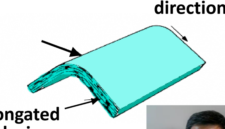
-
Thus bending should follow grain direction to reduce cracking Springback
When load is removed, there is some elastic recovery
= Initial bend radius = Final bend radius T = sheet metal thickness Y = yield stress E = elastic modulus
Compensation for springback
-
Overbending
-
Bottoming - Using high compressive pressure to reduce thickness at bend area
-
Stretch bending - Sheet metal is stretched beyond yield stress before bending over punch
-
Design change - incorporating ribs etc. to increase stiffness, reduce springback Bending force
T = sheet thickness k = constant L = width of bend W = die opening
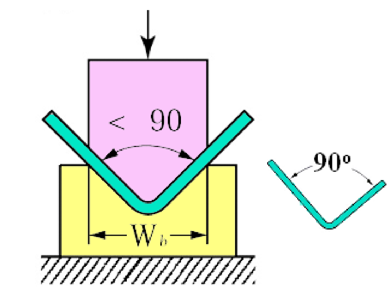
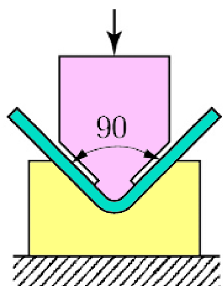
V-die bending Simple inexpensive die — Low production quantity — any angle — simple bending k = 1.33 Wiping die bending Complicated costly die — high production quantity — < 90only — precise bending k = 0.33
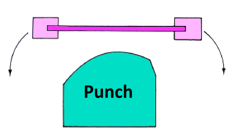
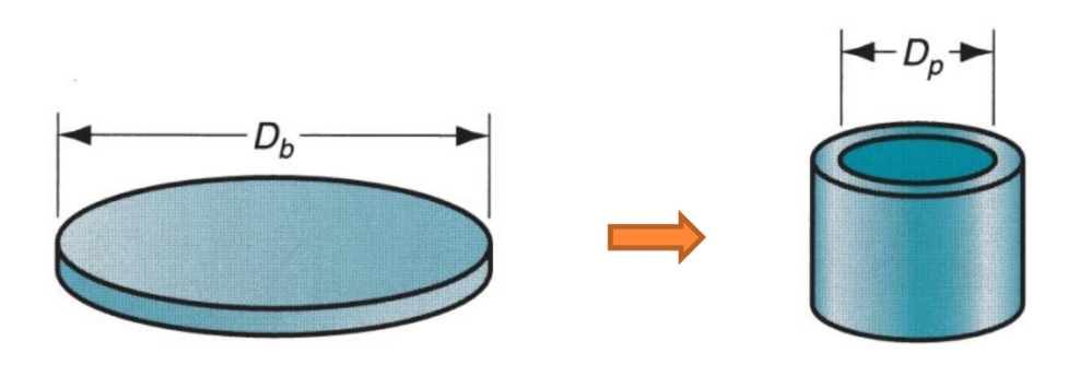
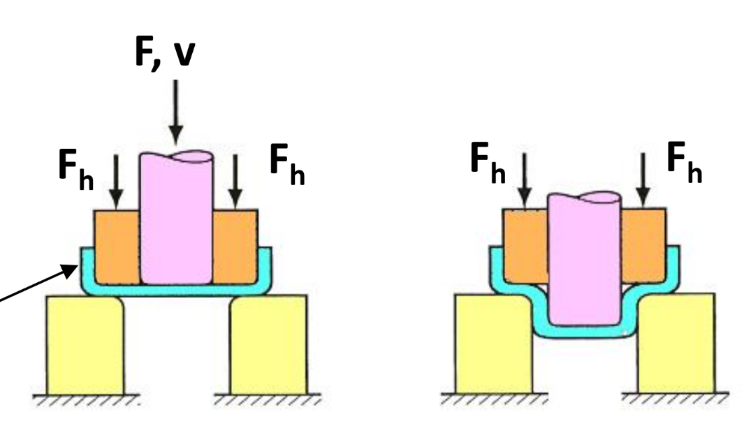
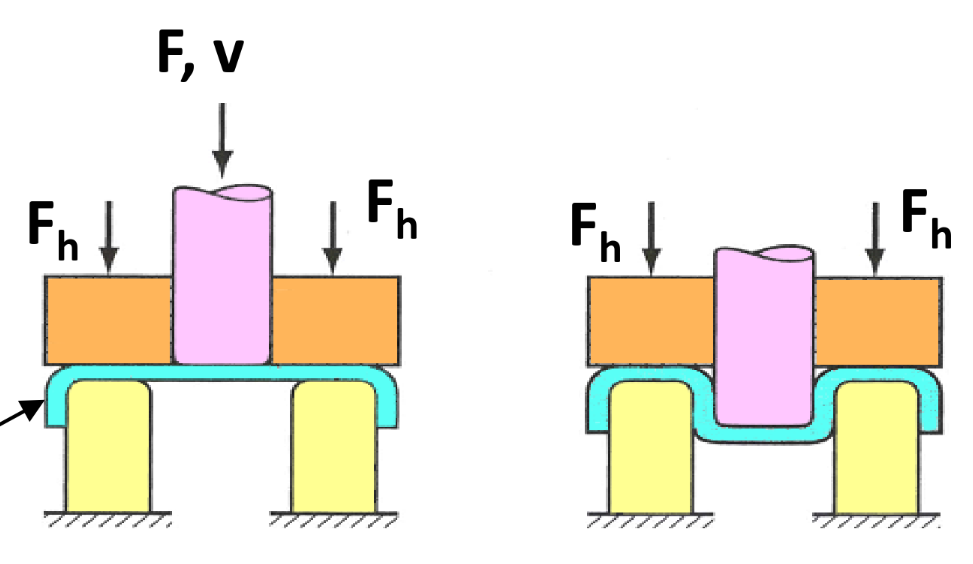
Deep Drawing
Forming smooth blanks into hollow parts (e.g. cans)
-
Deep drawing of cup
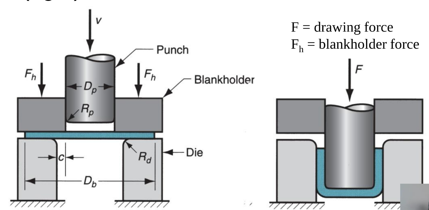
Clearance c = 1.1t — where t = sheet thickness Drawing sequence
- Punch makes initial contact with blank
- Downwards movement of punch bends blank along the die
- Straightening to form wall; tensile stress on wall
- Friction and compression; compressive stress on flange
- Final cup shape shows thinning in cup walls Stresses and defects
-
Compressive hoop stress (wrinkling)
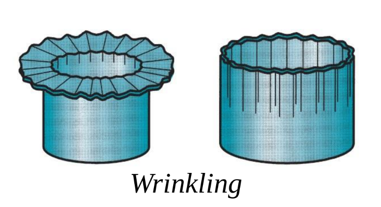
-
Perimeter reducing — Volume constant → Thickness needs to increase
-
Blankholder applies pressure to thicken and prevent wrinkles
-
Longitudinal tensile stress (tearing)
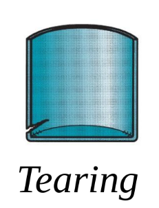
-
If blankholder pressure too high → metal held back from flowing into die cavity → tearing due to stretching
-
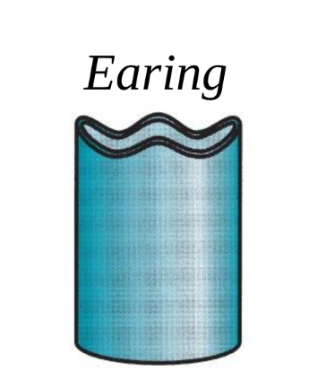
Earring (due to anisotropy)
Drawing feasibility Drawing ratio DR ≤ 2.0
 Reduction r < 0.50
Thickness-to-Diameter ratio
Redrawing
Reduction r < 0.50
Thickness-to-Diameter ratio
Redrawing
 Reverse drawing
 Requires lower force
Choosing blank size — Initial blank volume = final cup volume
Drawing force
F = maximum drawing force (N)
= punch diameter (mm)
= starting blank diameter (mm)
t = original sheet thickness (mm)
TS = tensile strength (MPa)
0.7 = correction factor to account for friction
Blankholder force
= blankholder force (N)
= die corner radius (mm)
Y = yield strength of sheet metal (MPa)
Requires lower force
Choosing blank size — Initial blank volume = final cup volume
Drawing force
F = maximum drawing force (N)
= punch diameter (mm)
= starting blank diameter (mm)
t = original sheet thickness (mm)
TS = tensile strength (MPa)
0.7 = correction factor to account for friction
Blankholder force
= blankholder force (N)
= die corner radius (mm)
Y = yield strength of sheet metal (MPa)
Metal Casting
Process: Molten metal flows by gravity (or other forces) into a mold cavity and solidifies there
| Advantages | Disadvantages |
|---|---|
| Complex parts | Limited mechanical properties |
| External and internal shape | Poor dimensional accuracy |
| Near net shape | Poor surface finish |
| Suitable for any sizes | Safety (hot metal) |
| Suitable for mass production | Environmental pollution |
Casting Mold
Two types: Open Mold & Closed Mold for complex geometry
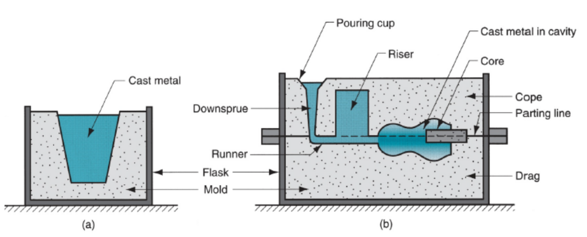
- Mold is made by packing sand around a pattern
- The Core is added to hollow the casting if needed
- The Riser is a reservoir of liquid metal that can fill the cavity during cooling shrink to prevent defects
Fluid Flow
Conservation of volumetric flow rate
Q = volumetric flow rate in
A = Cross sectional area in
v = velocity of flow in cm/s
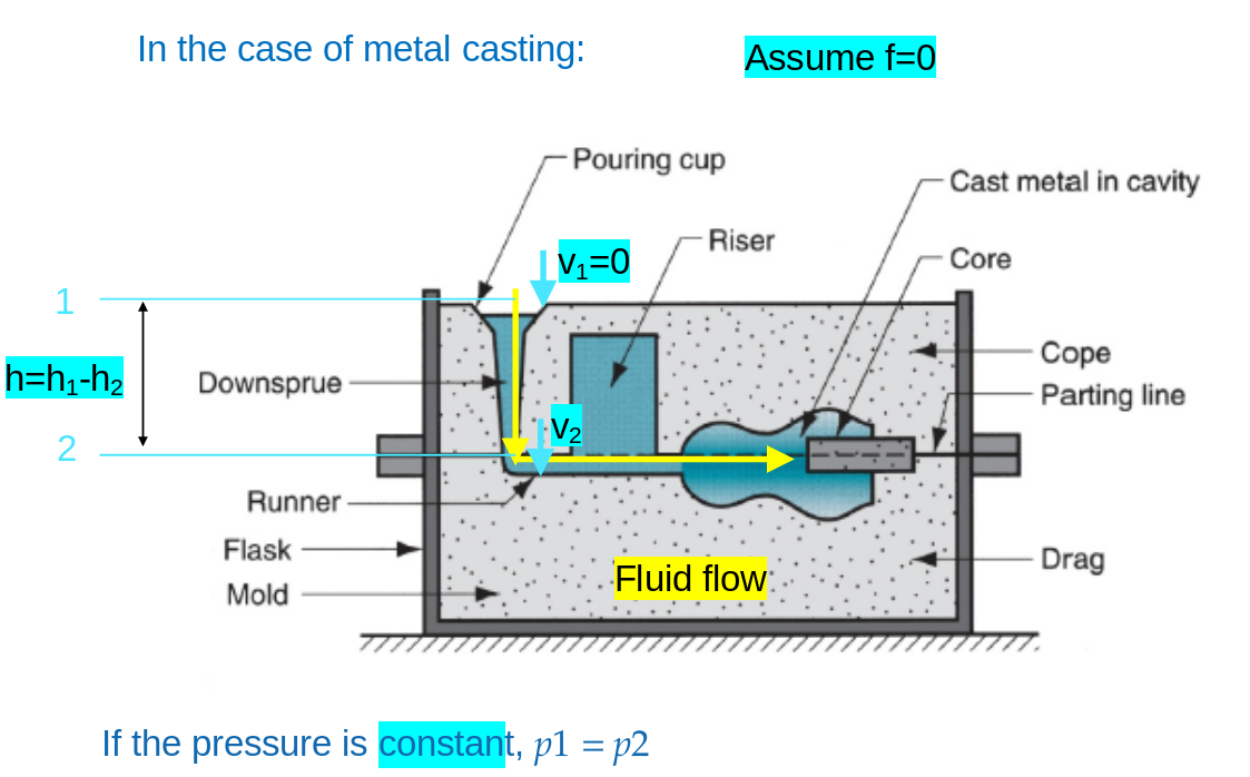 Bernoulli’s theorem for casting
Significance: To tune mold design to allow laminar flow, ensuring proper filling of mold cavity
Reynolds number — Laminar < 2000 — Turbulent > 20000 v = velocity of fluid flow d = diameter of channel
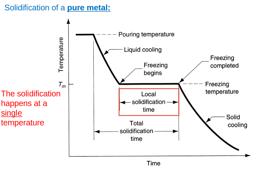
Solidification
For pure metal
 Randomly oriented grains near wall — Large columnar grains towards center — Outer skin due to mold cooling action
For metallic alloy
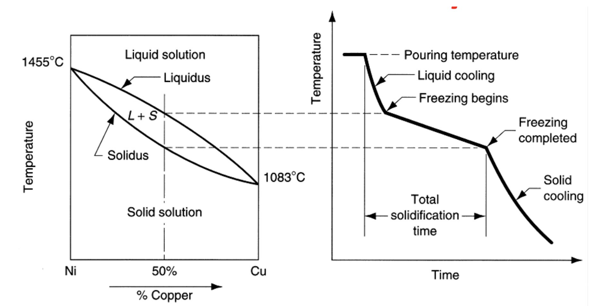 Same as pure metal + Segregation of alloying components at center of casting
Fluidity - capability to fill mold casting
Controlled by:
- Characteristic of molten metal
- Higher Viscosity, lower fluidity
- Higher Surface tension, lower fluidity
- Short Freezing Range, higher fluidity
- Inclusion in metal can have adverse effects
- Casting parameters
- Mold design — Mold material & surface properties — Rate of pouring — Heat transfer Spiral mold - test for fluidity Fluidity index ~ length of solidified metal in the spiral passage
Solidification time — Chvorinov’s rule
= total solidification time A= surface area of casting V= volume of casting = mold constant n = exponent with typical value = 2
It tells us: 1) How much metal is needed to fill the mold — 2) time taken to solidify
Shrinkage
Due to: Liquid contraction — Solidification shrinkage — Solid contraction
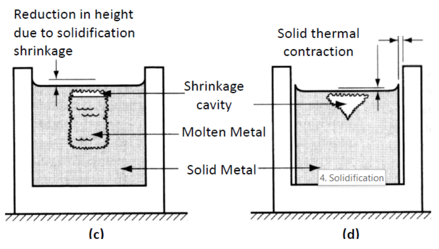 Mold is made bigger to compensate shrinkage — pattern shrinkage allowance
 Exception: cast iron with high C% → graphitization causes expansion counteracting shrink
Countering shrinkage - Directional solidification
Exception: cast iron with high C% → graphitization causes expansion counteracting shrink
Countering shrinkage - Directional solidification
- Constant supply of liquid metal due to riser
- Solidification progress from distant regions to riser
- Orientate parts that have lower V/A away from riser
- Riser design should maximise V/A while minimising volume (waste)
Common defects and design consideration
-
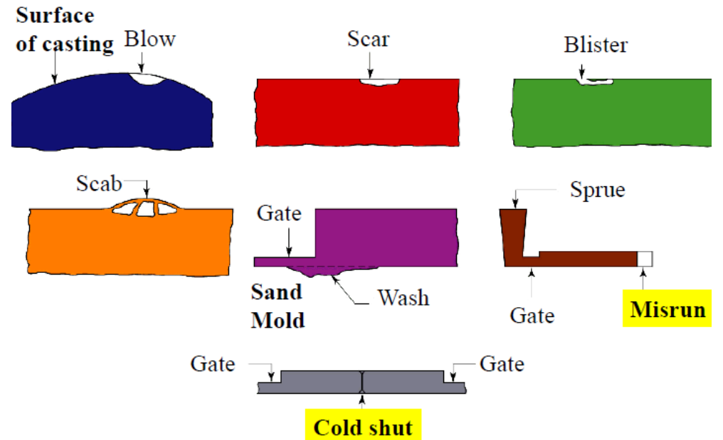
Blow, Scar, Blister, Scab, Wash, Misrun, Cold shut, inclusion, Shrinkage porosity
-
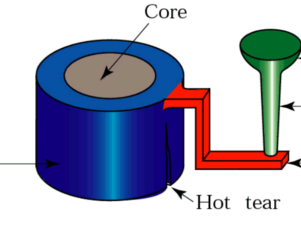
Hot tear
-
Due to inability to shrink freely, To prevent:
- Exothermic compounds in critical sections
- External / Internal Chills (Parts that extend out in increase A) General design considerations
- Geometric simplicity
- Avoid sharp corners — hard to fill
- Have draft angles — easier to remove
- Avoid hot spots + use small cores to displace cavities
- Try to maintain uniform cross -section
Metal casting process
Expendable mold
Sand casting
- Poor dimensional accuracy and tolerances
- Simple and widely used Investment casting (lost wax process) Wax pattern is coated with refractory material then melted away for a precise mold
- Mold is heated to a high temperature allowing contaminant are eliminated and liquid metal flows easily
- Mold is broken away after
- Advantages: Complex parts — Accurate & good surface finish — reuse wax — no additional machining
- Disadvantages: Many processing steps — expensive
Permanent mold
- Mold is openable — preheat and coat — cores inserted before closing and pouring
- Advantages: Accurate & good surface finish — stronger castings due to finer grains
- Disadvantages: Low melting point metals only — Simple geometry — Expensive mold Die casting
Molten metal injected under high pressure into molds called dies
- Cold Chamber machine

- Hot Chamber Machine
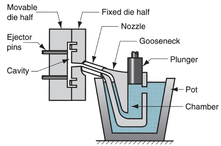
- Advantages: Mass production cost — Accurate and good surface finish — Thin section possible — rapid cooling = stronger
- Disadvantages: Low melting pt only — limited geometry to allow removal
Metal Machining
Subtractive manufacturing process where material is removed from the workpiece to attain desired final product
Fundamentals of machining
Cutting theory
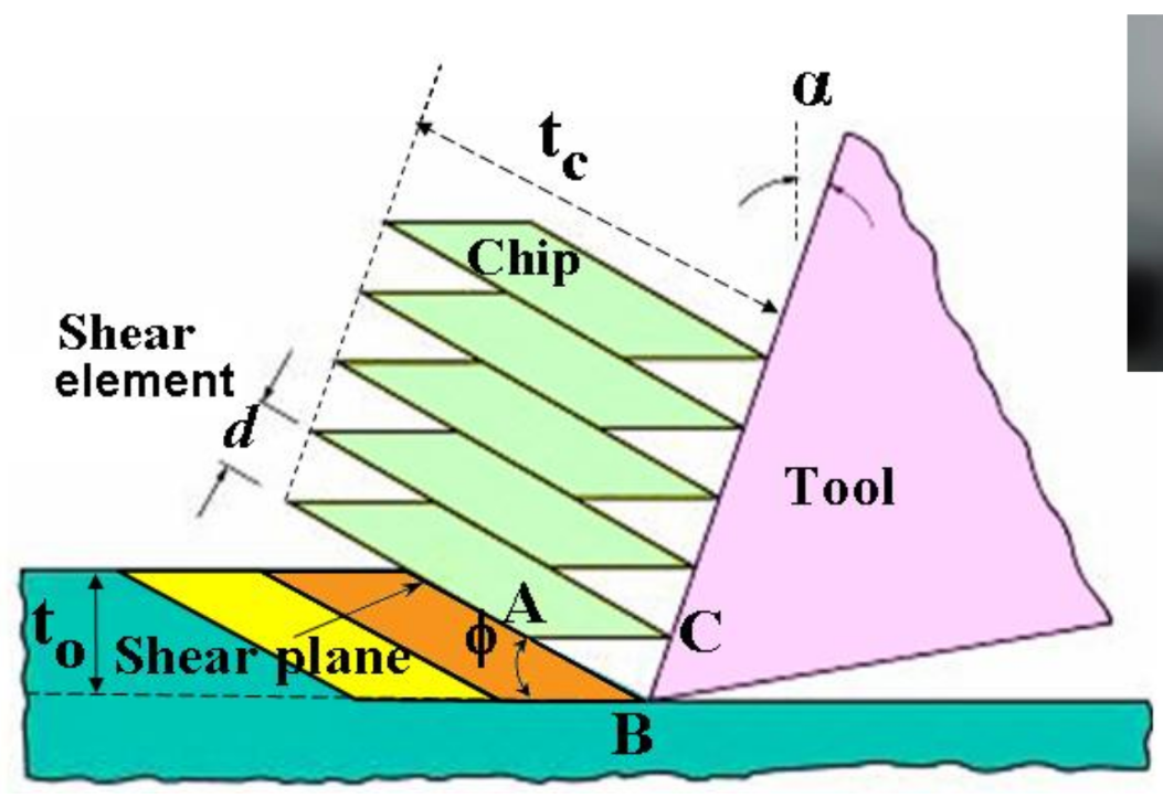
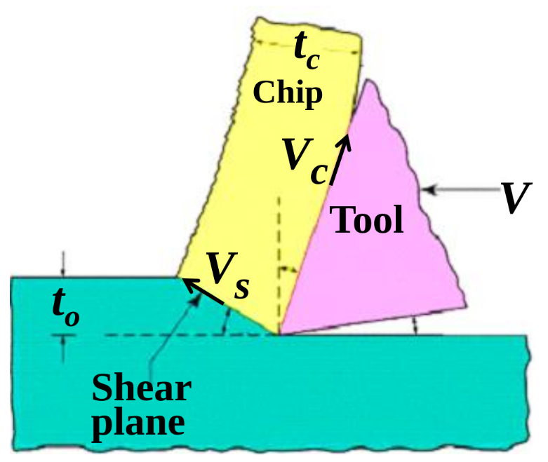
Orthogonal cutting model
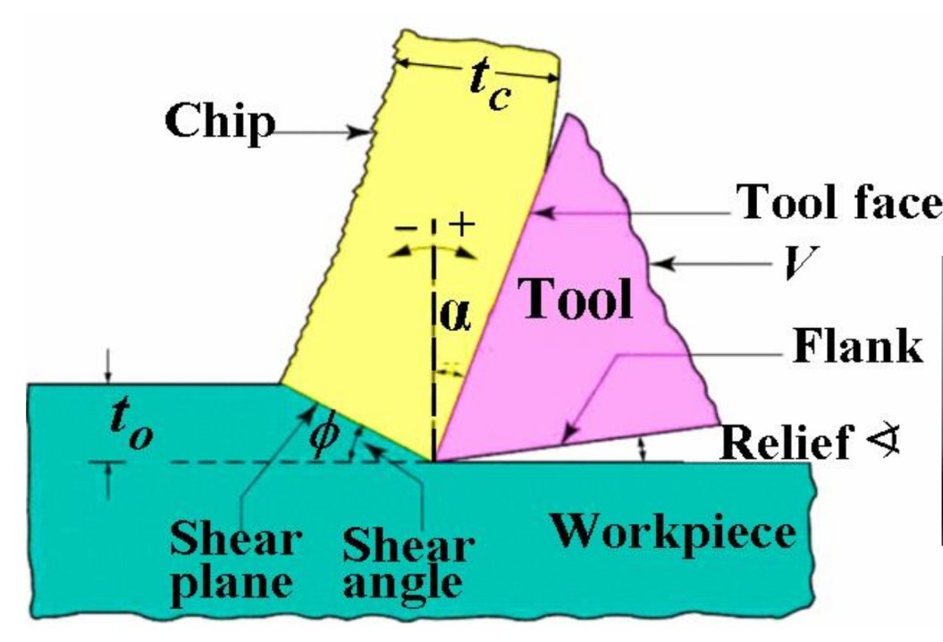 = shear angle
= undeformed chip thickness
= chip thickness
= shear angle
= undeformed chip thickness
= chip thickness
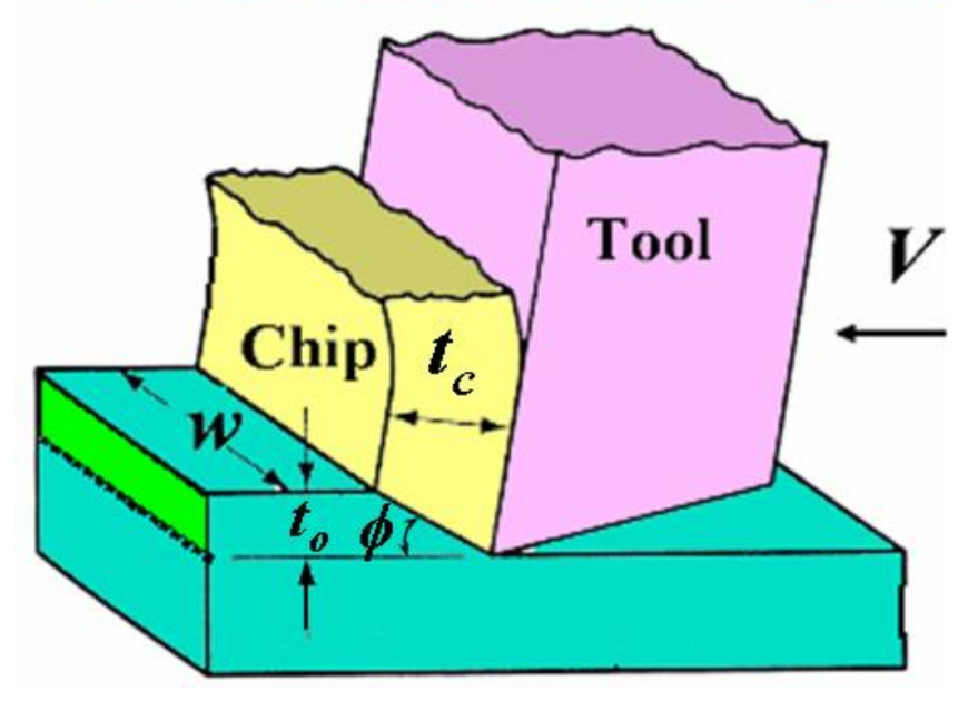 V = cutting velocity
= rake angle
w = width of cut
V = cutting velocity
= rake angle
w = width of cut
Mechanics of chip formation (shearing)
Cutting forces (Merchant circle & Shear angle)
 Cutting force
Thrust force
Friction force F
Normal force N
Shear force
Normal to shear
Resultant force R
Cutting force
Thrust force
Friction force F
Normal force N
Shear force
Normal to shear
Resultant force R
- same magnitude and colinear in all 3
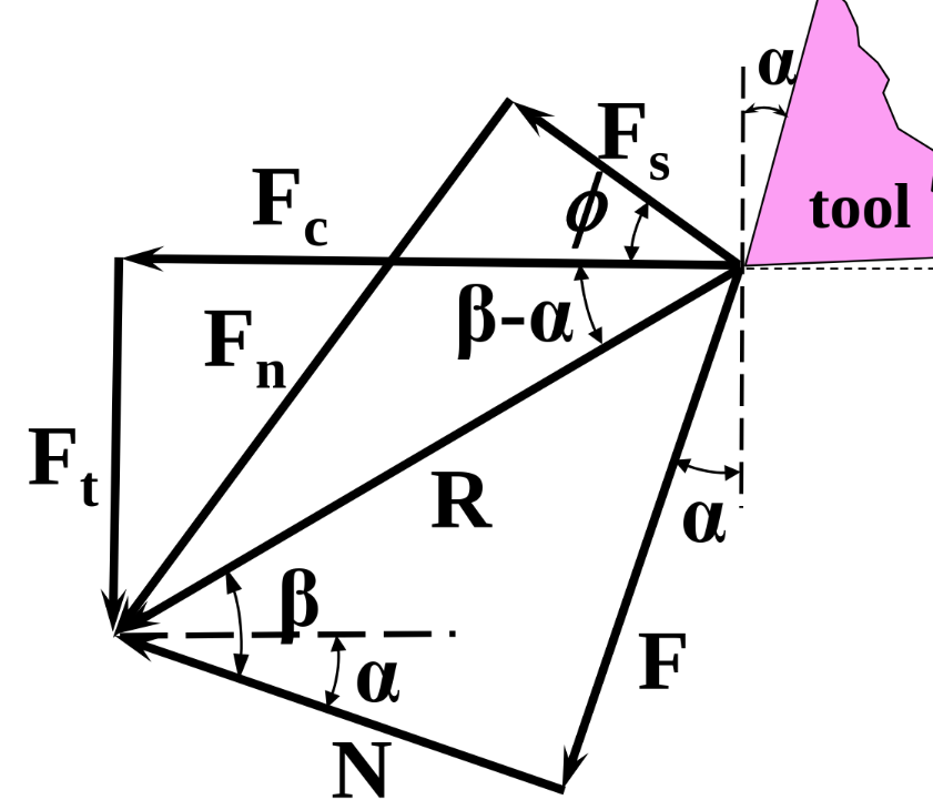 Friction angle & coeff of friction
Shear stress
Merchant equation — can only be used if given in question
Friction angle & coeff of friction
Shear stress
Merchant equation — can only be used if given in question
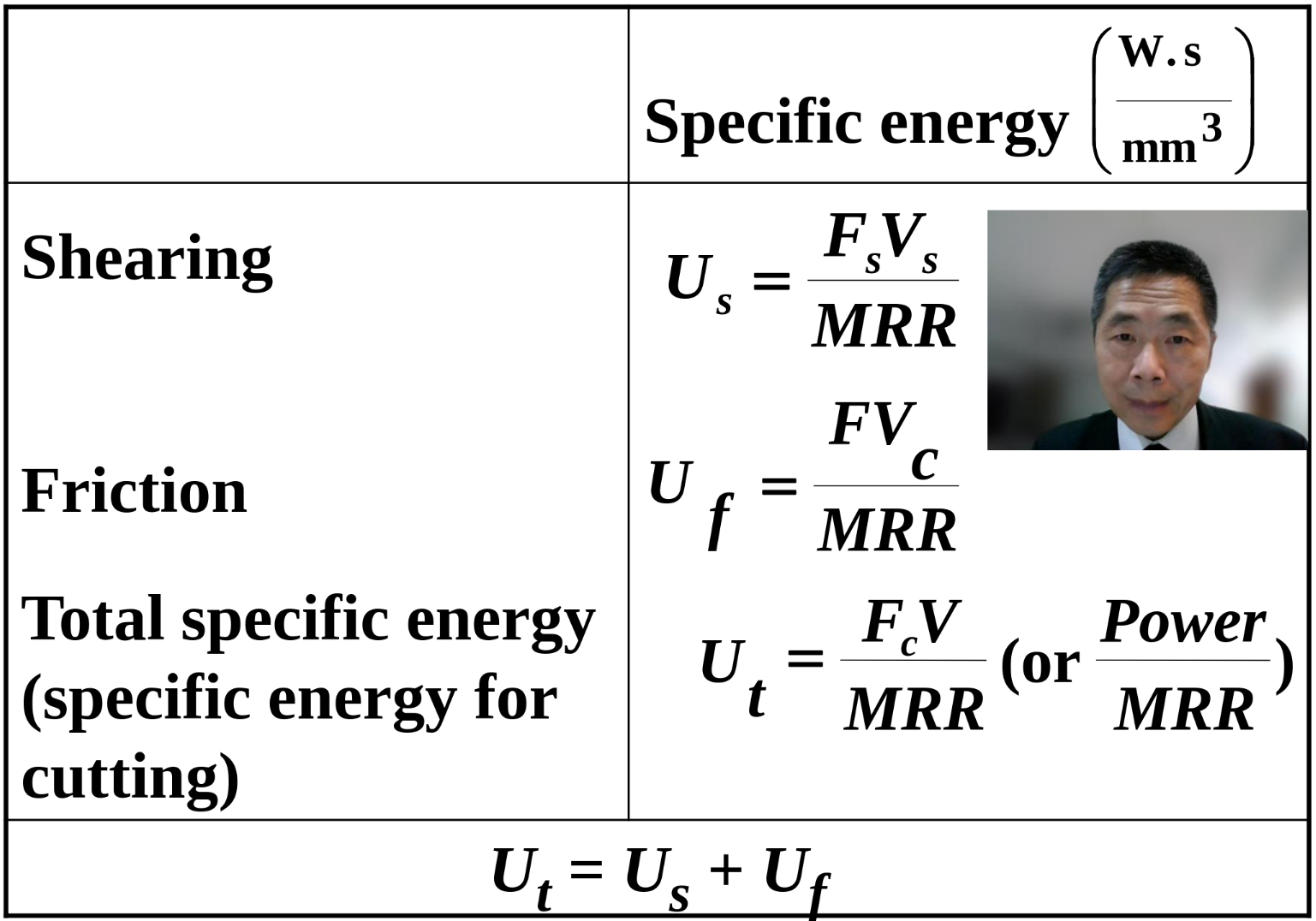
Power and Energy Relationship in machining
Power is dissipated in shearing plane to shear the material and interface plane to overcome friction
 Power(Cutting) = Power(shearing) + Power(friction)
MRR (Material removal rate) =
Energy of removing unit area of material
Power(Cutting) = Power(shearing) + Power(friction)
MRR (Material removal rate) =
Energy of removing unit area of material
Cutting tool technology
Tool wear and Tool life
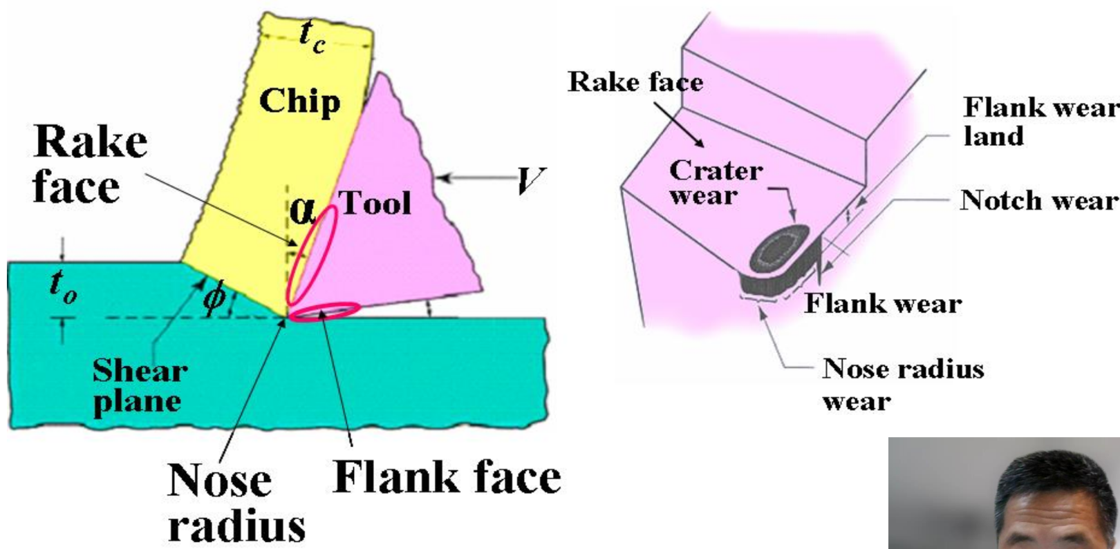 Flank wear - Flank face
- Rubbing of tool on surface
- High temperature affecting properties of tool material Crater wear - Rake face - Tool chip interface
- Temp at tool chip interface
- Chemical affinity between tool and wp material — diffusion mechanism When to replace tool?
- Maximum flank wear reached
- Workpiece surface finish becomes worse
- Cutting force or Temperature increase significantly
Taylor’s Tool Life Equation
V = cutting speed (m/min) n = exponent (<1) T = tool life (min) C = constant
n and C values depend on live conditions Extended equation — for rotating cutter d = depth of cut (mm) f = feed (mm/rev)
x and y are determined experimentally
Temperature when cutting
Shearing and friction creates heat
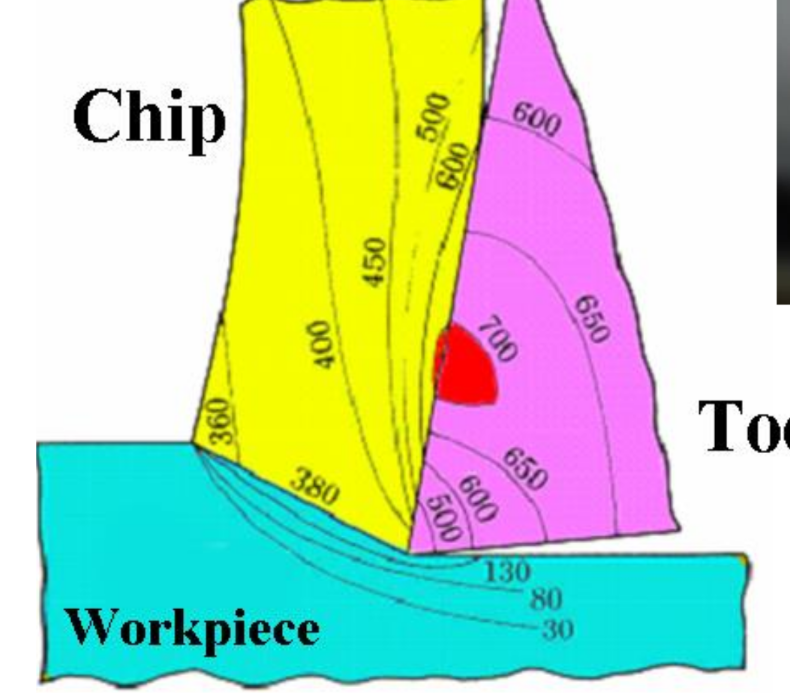 Adverse effects on:
- Machine tool
- Temps distort components — difficult to control dimension
- Workpiece
- Temp distort w/p — ruins dimensional accuracy and tolerance
- Temp damage machined surface — early part failure
- Cutting tool
- Strength drop
- Hardness drop
- wear resistance drop
Cutting fluid
Lubricant — reduce friction
Coolant — reduce heating effects
Cutting tool — Material selection
Hot hardness — hardness of tool at cutting temp is maintained Toughness & impact strength — prevent chipping/fracturing during impact and vibration Thermal shock resistance — withstand rapid cooling cycles
Chip types and surface finish
Chip types
Continuous chips
- Ductile material @ high speed
- good surface finish
- tangle around workstation
Change machining parameters or chip breakers to remedy Discontinuous chips
- Brittle material / hard inclusions or impurities present
- Cutting force varies during cutting Built-up edge (BUE)
- Layer of material get deposited on the tool until it breaks up
- Part of it leaves with the chip and the rest is deposited on the w/p, creating a rough finish
- The depositing on the tool changing the cutting edge and ruins the surface finish Serrated chips
- Saw tooth like appearance due to strength that decrease with temperature, e.g. titanium
Surface finish
Roughness parameter: Factors affecting
-
Feed marks left by cutting operations
R_t = \frac{f^2}{8R}$$ f = feed (mm/rev) R = tool nose radium (mm) -
Vibration
- Force vibration — periodic vibration due to tool usage
- Self-excited vibration — due to disturbance of cutting zone - could leading to chipping / premature failure of cutting tool
Material removal process
Turning — Round shapes
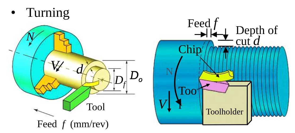 V = Cutting speed (m/min) N = Rotational speed (rev/min)
Material removal rate —
Cutting speed —
Procedure for good finishing — Rough cuts at high MMR, Finishing cut at low MMR
V = Cutting speed (m/min) N = Rotational speed (rev/min)
Material removal rate —
Cutting speed —
Procedure for good finishing — Rough cuts at high MMR, Finishing cut at low MMR
Drilling
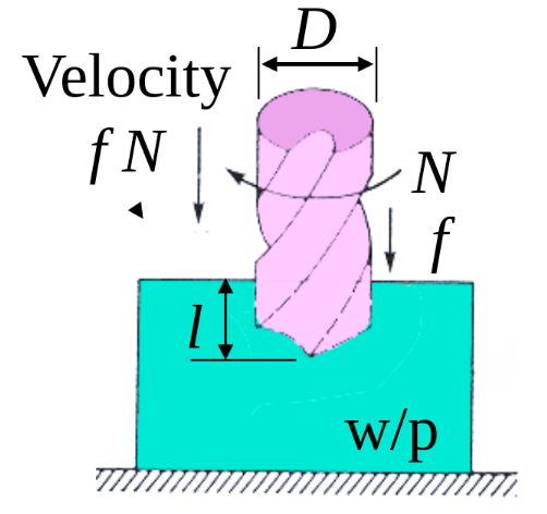 Material removal rate —
Cutting time —
Cutting speed =
Power = Torque (Nm) x rotational speed of drill (rad/s)
Material removal rate —
Cutting time —
Cutting speed =
Power = Torque (Nm) x rotational speed of drill (rad/s)
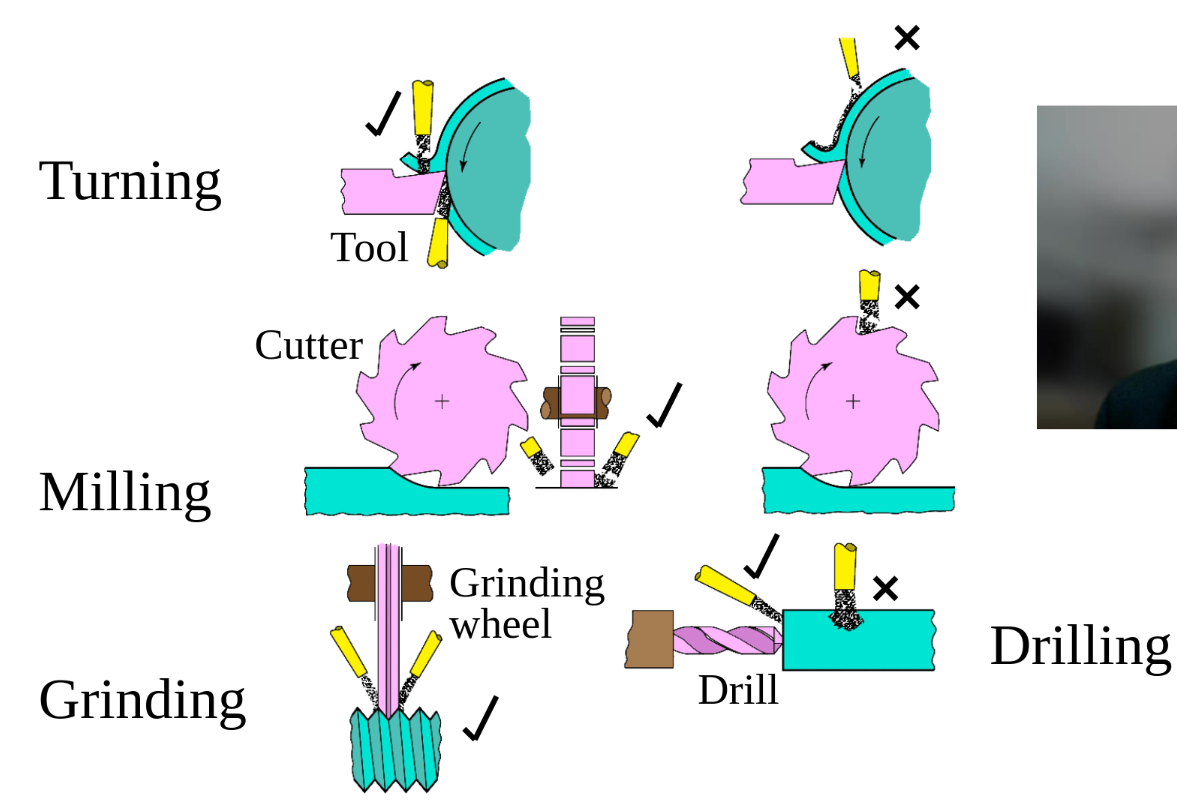
Milling
Conventional milling — up milling
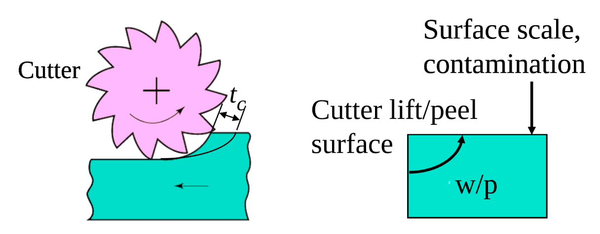
- chip thickness and surface scale do not affect tool life
- w/p require proper clamping as it will be pulled upwards Climb milling — down milling
- Maximum chip thickness at start of cut — not good
- Downwards cutting holds workpiece in place
- Abrasive surface scale can damage/wear cutter
- High impact forces — rigid setup required
Metal Joining
Fundamental of Welding
Joining parts with heat or pressure
Type of welding
Fusion welding — Join by melting base material
- Filler material can be added to facilitate process and increase bulk / strength
- Oxyfuel gas welding (OFW)
- Melt using oxyfuel gas — e.g. acetylene
- Arc welding (AW)
- Melt using electric arc
- Laser Welding Solid state welding (SSW) — Join using pressure mainly or alone
- No melting, no filler metal
- Forge welding
- Ultrasonic wire bonding
Physics of welding
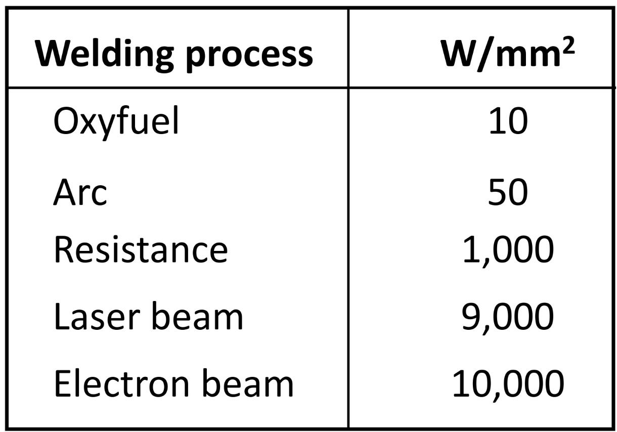
Aim: To melt metal with minimum energy but high power density
Power density (PD — W/mm^2)
P = Power entering surface (W) A = Surface area energy entering (mm^2)
 Unit energy for melting — To heat up + melt
= Melting temp of material (K)
Heat transfer — Not all input energy used for welding
Heat transfer efficiency,
Unit energy for melting — To heat up + melt
= Melting temp of material (K)
Heat transfer — Not all input energy used for welding
Heat transfer efficiency,
- Heat received at work surface / heat generated at source
- Depends on source Melting efficiency,
- Heat used for melting / Heat received at work surface
- High thermal conductivity metals like Al and Cu have low efficiency here Energy Balance Equation If time is considered: V = volume of metal melted (mm^3) WVR = Welding volume rate (mm^3/min)
Welding Process & Features
Arc Welding — Fusion Welding
Coalescence of metals by an electric arc between electrode and work
- ~5500 degree celcius — melt any metal
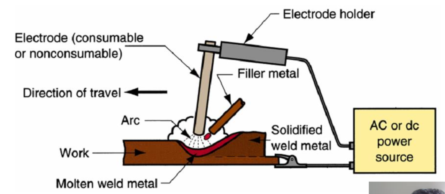
Arc shielding - prevent metal from reacting with air in this process and degrade
-
Shielding gases (Argon, helium, CO2 …)
-
Flux
- Prevent formation of oxides + dissolves oxide for removal
- Provide protective atmosphere for welding
- Stabalizes arc, reduces spattering
- Application methods: Direct pouring, coated electrode, tubular electrode
-
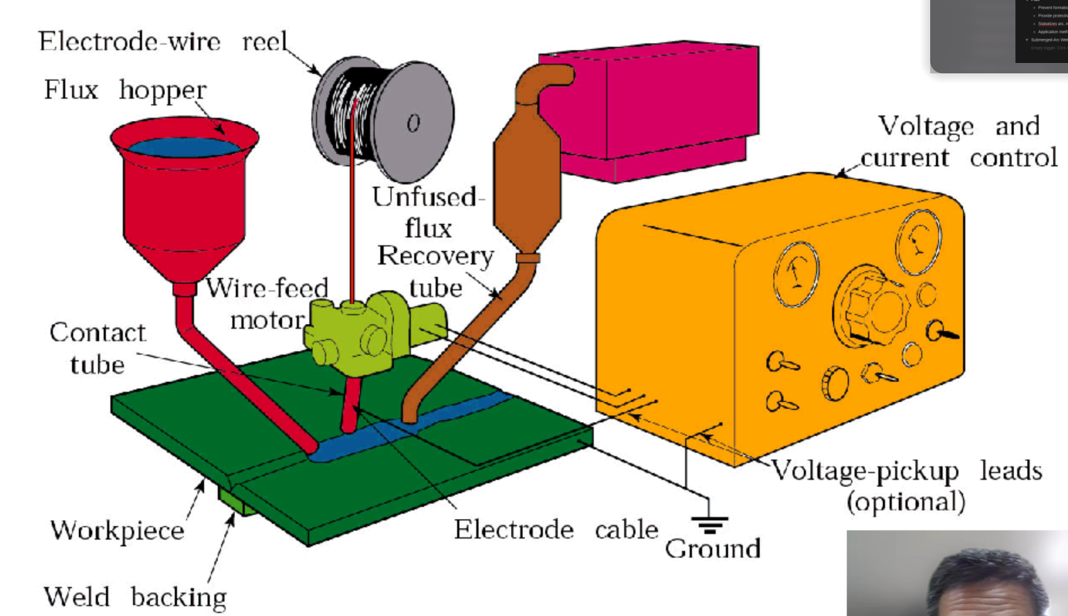
Submerged-Arc Welding
-
Shielded-Arc Welding
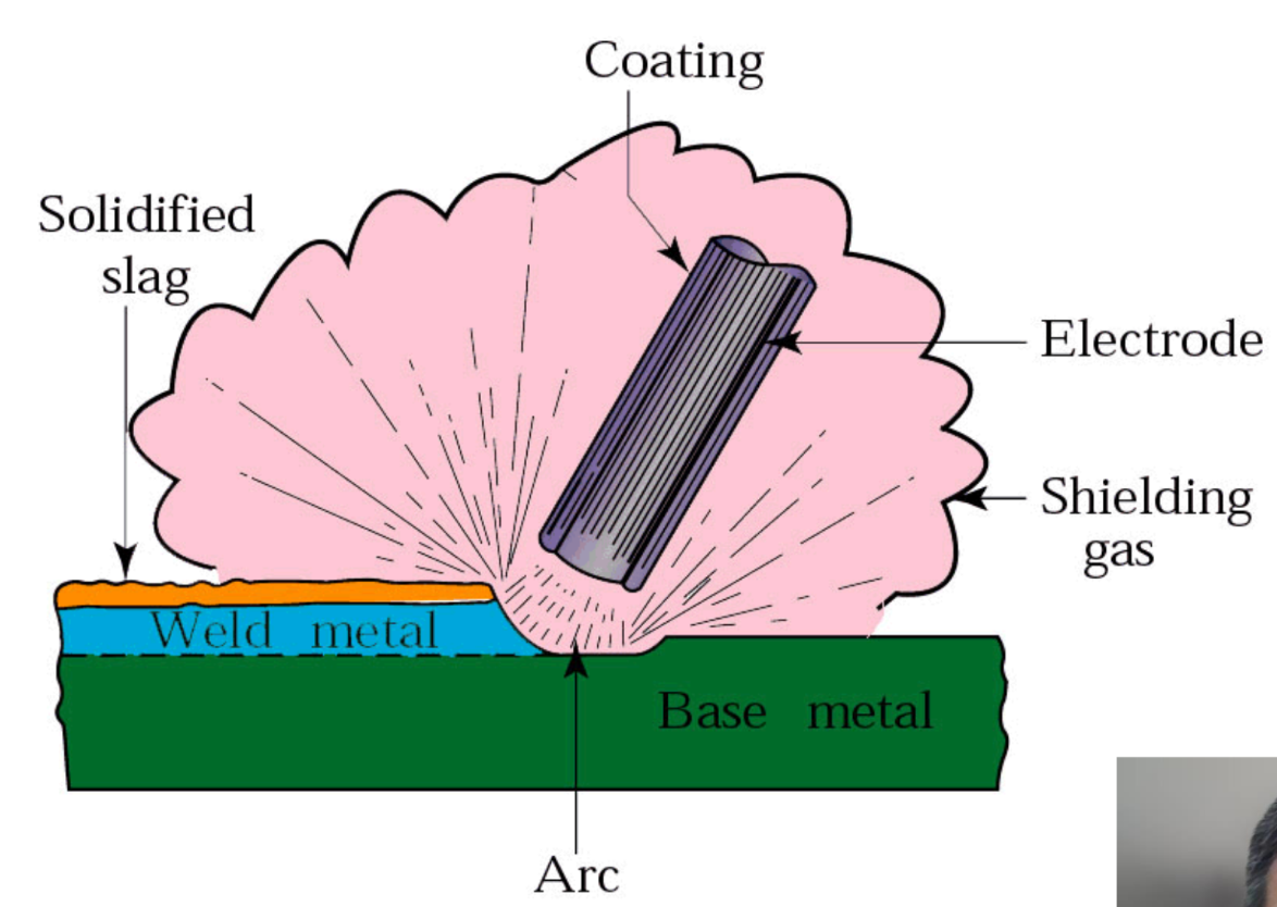
Types of electrodes
Consumable electrodes
- Welding rods/sticks, must be changed often
- Weld wire, continuously fed from spools
- Both consumed and added as filler material Non-Consumable electrodes
- Tungsten — resists melting — 3410 celcius
- gradually depleted by vaporization
- May not have filler
Non-consumable electrode processes
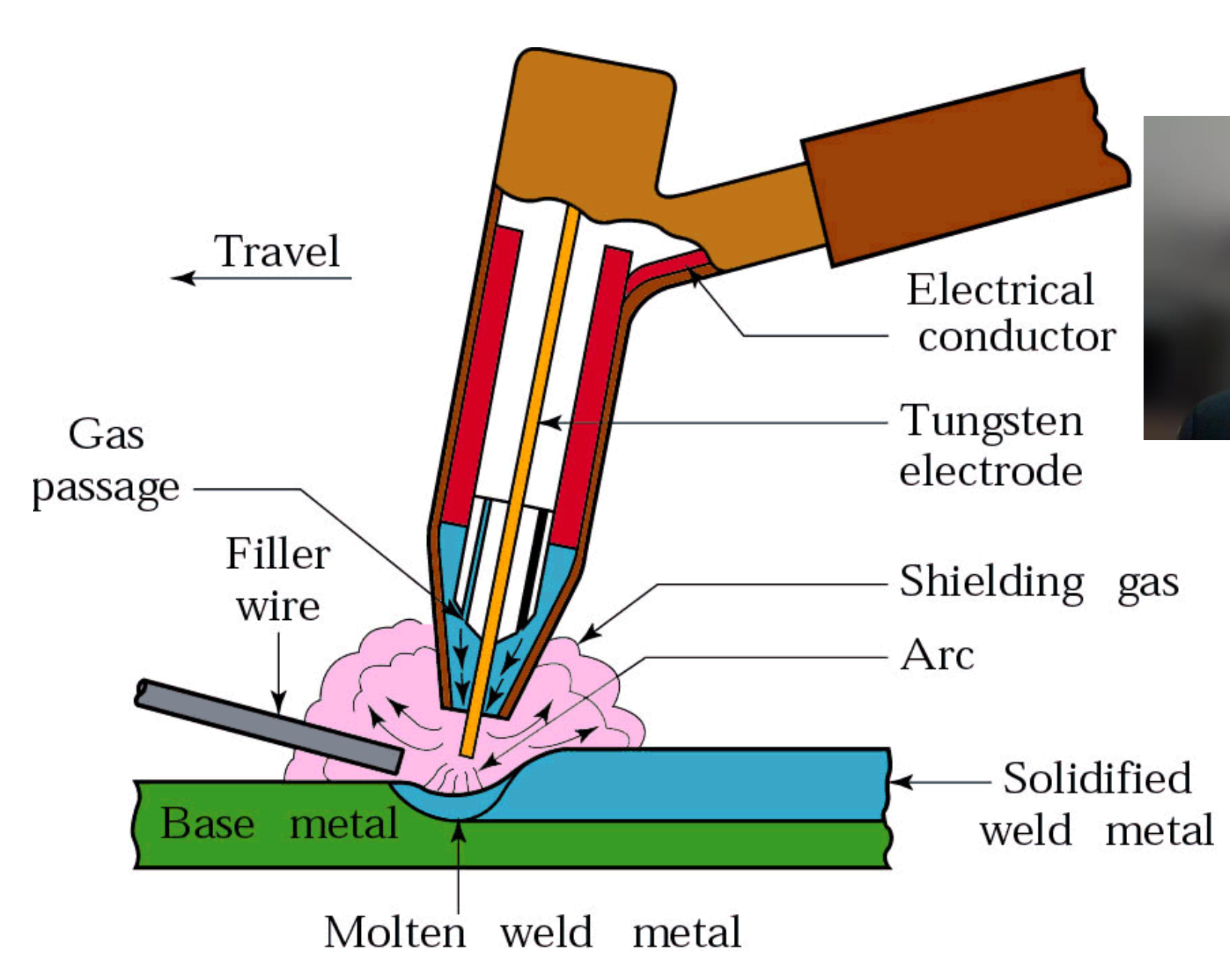
Gas Tungsten Arc Welding (GTAW)
- Tungsten electrode + inert gas shielding
- AKA TIG welding (Tungsten Inert Gas Welding)
- Application: aluminum and stainless steel
Electrical Resistance Spot Welding
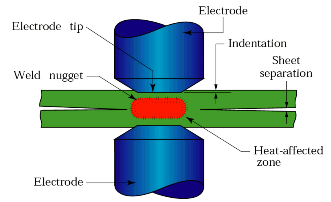
- Heat generated from electrical resistance welds sheets together
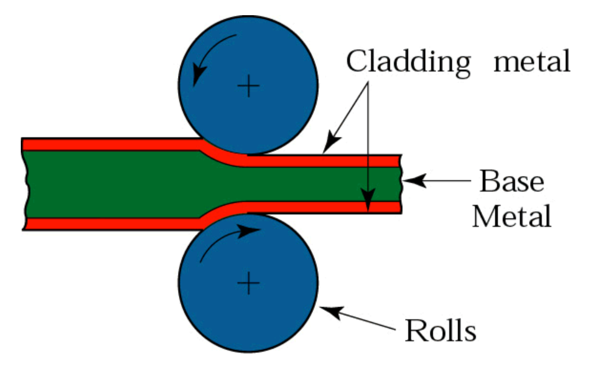
Roll Bonding — Solid state welding
Friction Welding — Solid state welding
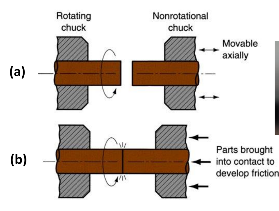
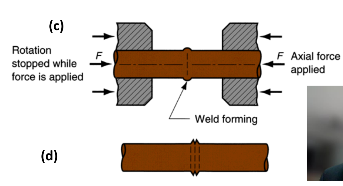
- Fused using frictional heat and pressure
- No filler or shielding normally used
- No melting is correctly done
- usable for dissimilar metals
- widely used for mass production
Explosive welding — Solid state welding
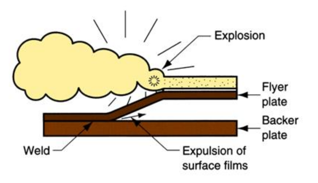
- Can bond dissimilar metals — creates wave like interface pattern
Weld Quality
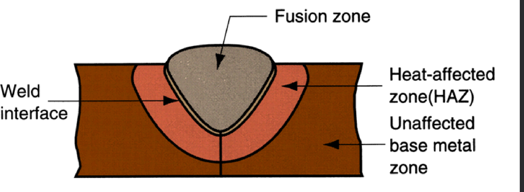
Heat affected zone (HAZ)
- Experienced temps high enough to cause micro structural changes
- No difference chemically
- Normally negative (e.g. brittle)
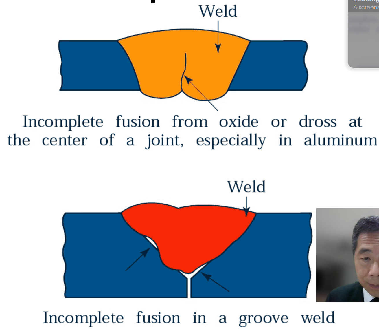
Incomplete Fusion
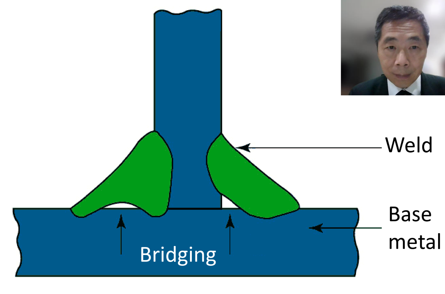
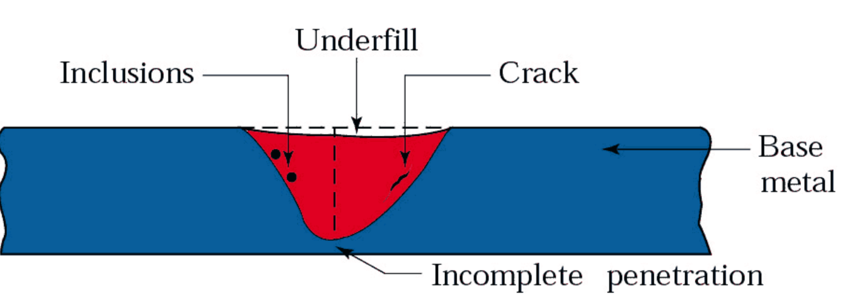
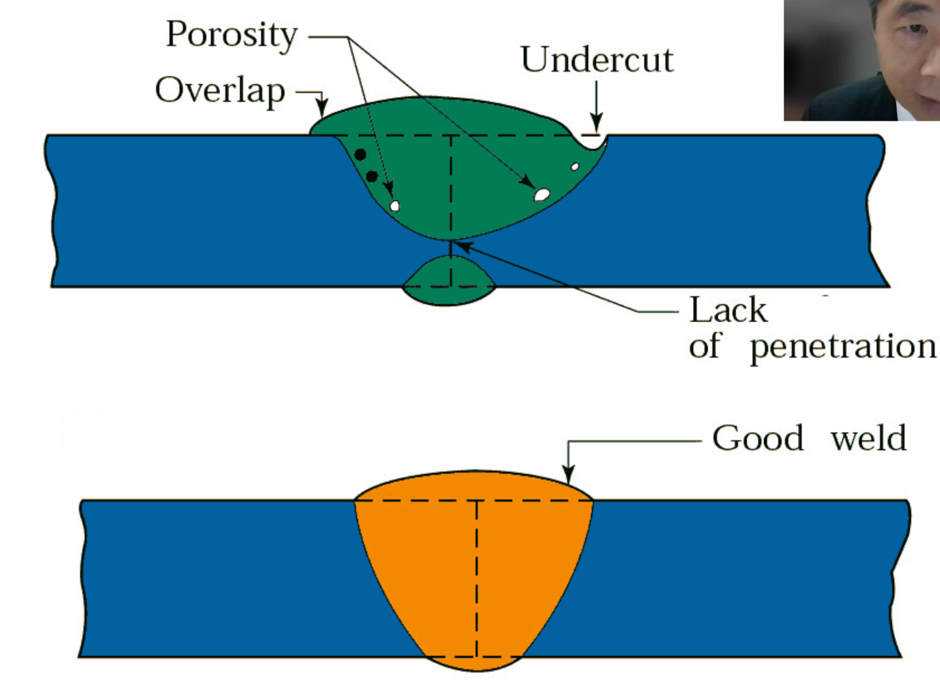
Poor weld profile
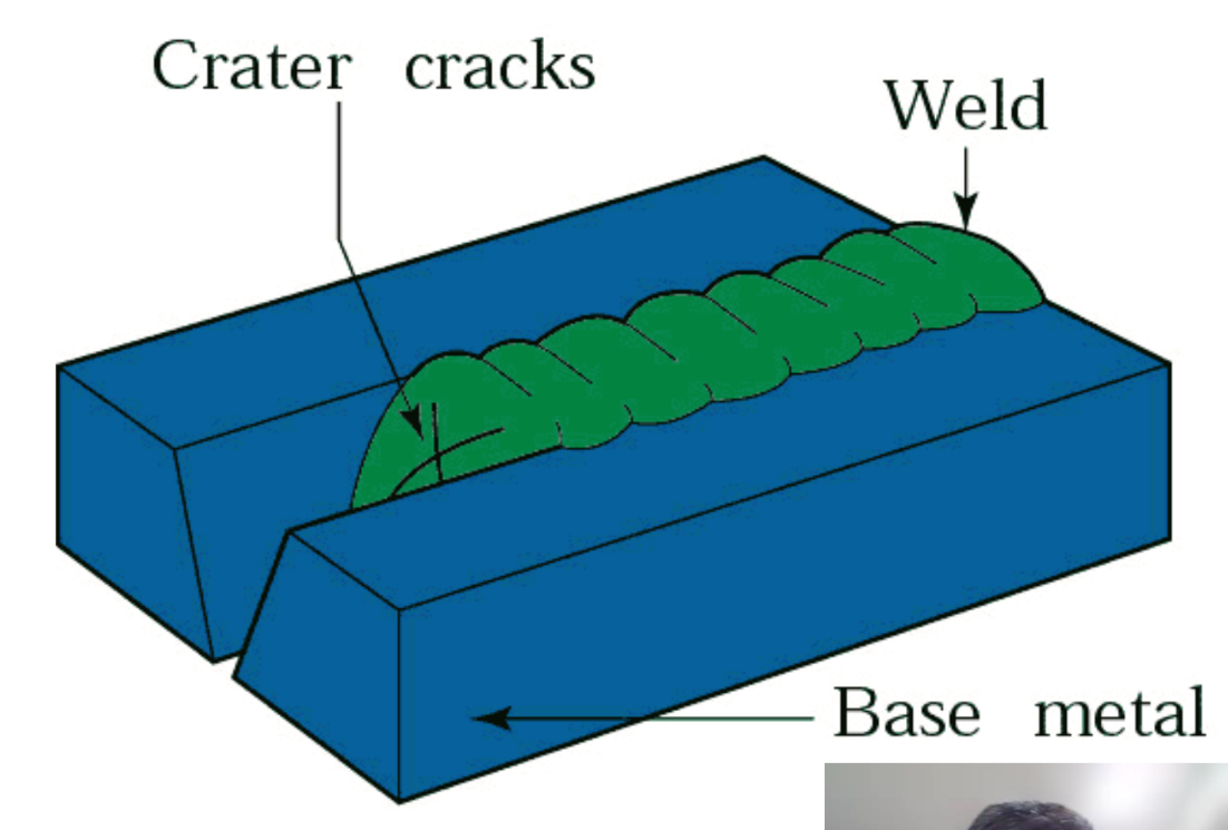
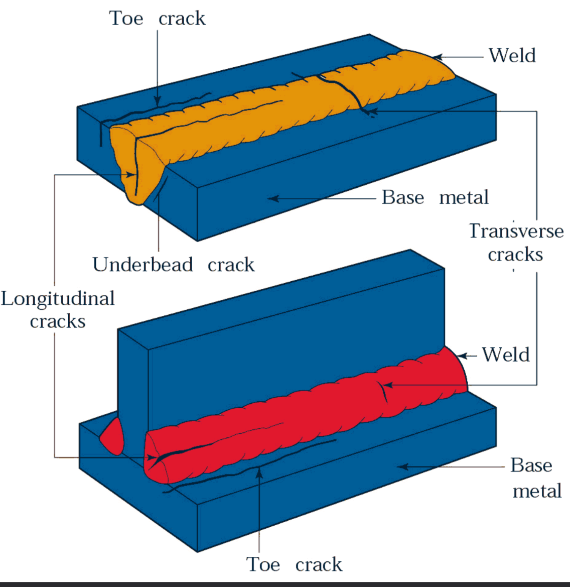
Cracks in Welded Joint
- Due to thermal stress from temp gradients
- Variation in composition
- Embrittlement of grain boundaries
- Hydrogen embrittlement
- Inability to contract — tensile stress
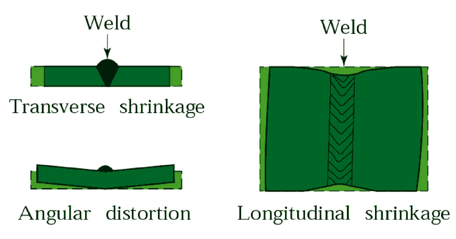
Distortion after welding
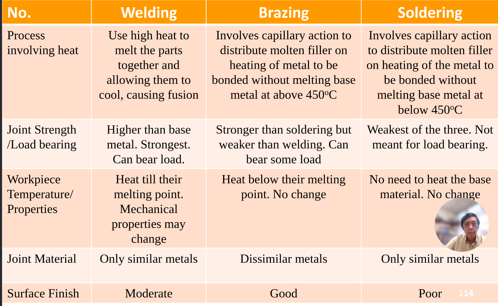
Brazing, Soldering and Adhesive Bonding
Brazing
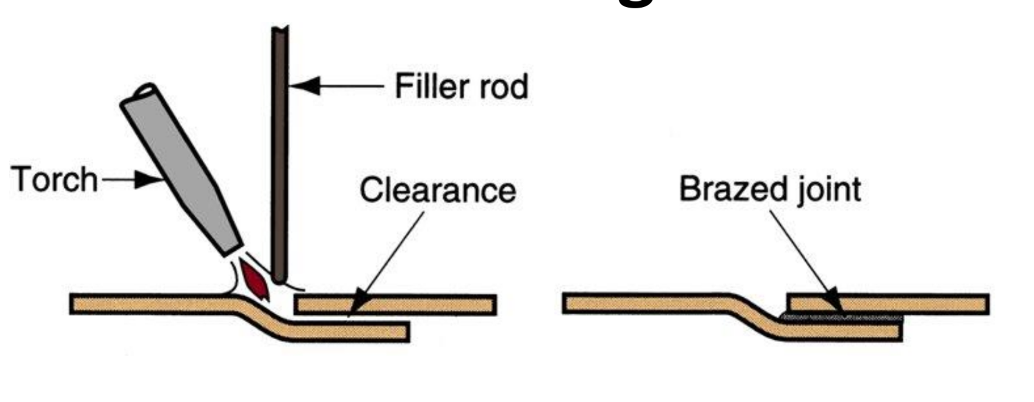
- Low melting pt, >450 celcius
- Only filler metal Why brazing? — Poor weldability between metals (Dissimilar / metal + ceramics) Brazed Joints design — Maximise contact area
Soldering
- Same as brazing but lower than 450 celcius
- Filler metal = Solder
- Mainly for electronics assembly
Adhesive Bonding AKA glue
- Can bond basically all materials
- Require maximised contact area for good joining