Limits and Fits
Limits terminology
- Basic size = Theoretical size — e.g. 48.00
- MMC for shaft/hole — Nicest value / least d.p
- Tolerance notation — 48.00 ± 0.02
- Tolerance = difference between limits of size — e.g. 0.04
- Limits of size = Largest and Smallest size permitted — 48.02 (largest) 47.98 (smallest)
- Actual size = measured size
- Maximum material condition (MMC) — limit of size resulting in maximum material involved
- Minimum material consition (LMC) — limit of size resulting in minimum material involved
Fits terminology
- Clearance fit — worst case scenario will still have clearance — size range do not overlap
- Interference fit — all cases have interference — size range always overlap
- Transition fit — cases can either have clearance or interference — partial overlap of size range
- Upper deviation =
- Lower deviation =
- Fundamental deviation — deviation closest to basic size
- Allowance =
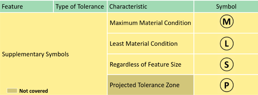
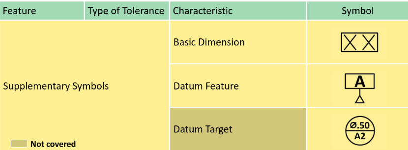
GD&T Fundamental
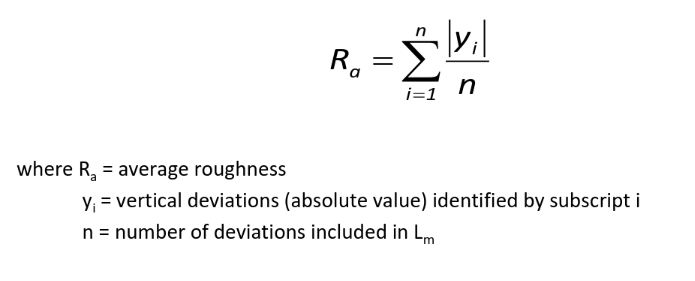
Surface texture
Notations
-
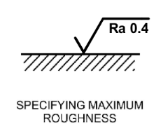
Specifying max roughness
-
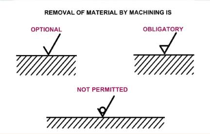
Removal of material instructions
-
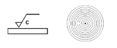
Lay symbol =
-
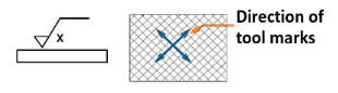
Lay symbol X (honing)
-
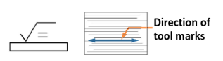
Lay symbol C (turning)
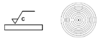
-
Specifying max & min roughness
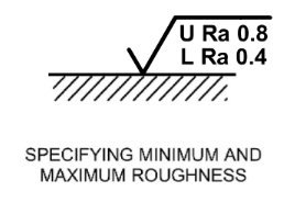
-
Machining allowance
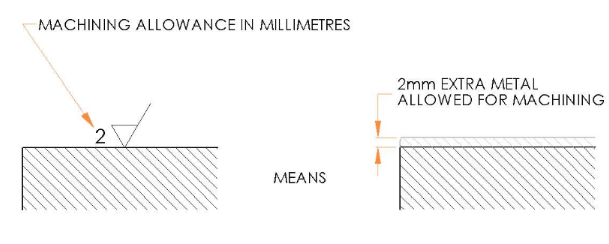
-
Lay symbol (grinding / shaping)
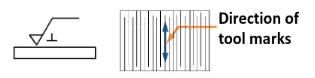
-
Lay symbol M (lapping)
-
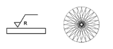
Lay symbol R
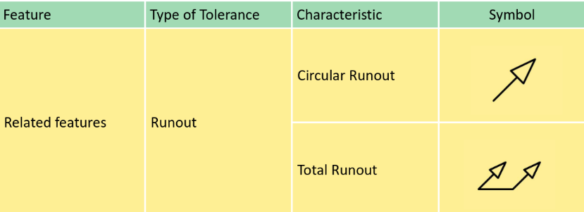
Tolerances
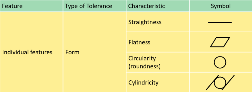
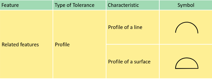
Form tolerances
Straightness
For parallel line element on surface, its allowed to vary in depth within straightness tolerance
- Flatness: Same as straightness but for surface Virtual condition (VC) VC = MMC (Shaft) + Geometric tolerance
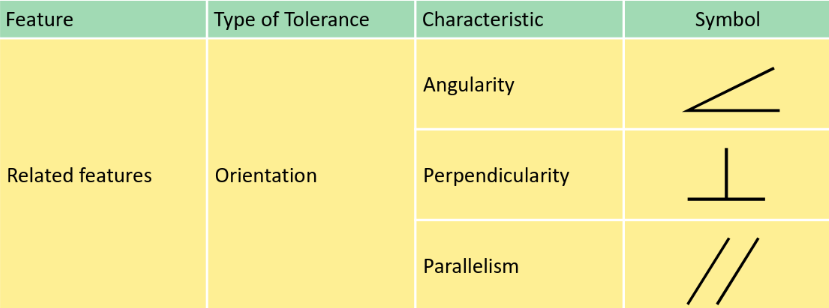
- The modifier allows the feature surface(s) to exceed the maximum material boundary by the amount of form tolerance, meaning that VC = MMC + tolerance. Angularity
Deviation of the angle of a feature — e.g. center line of hole
- Parallelism and Perpendicularity is similar
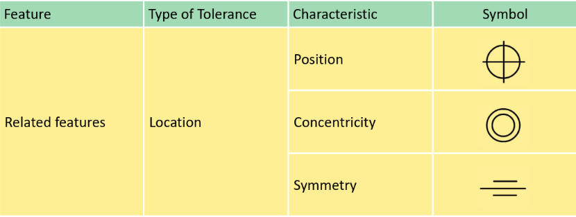
Location tolerance
Position