Orthographic Projection
Drawing Standards
Line types:
-
Visual Aid
| A | Thick Continuous | Visible outlines & Edges |
| B | Thin Continuous | Dimension, Projection line, Hatching line |
| C | Thin Short dashes | Hidden outlines & Edges |
| D | Thin Chain | Centre lines, Pitch lines |
| E | Thin Chain, Thick Ended | Cutting plane |
| F | Thin continuous Irregular | Limits of partial view / sections |
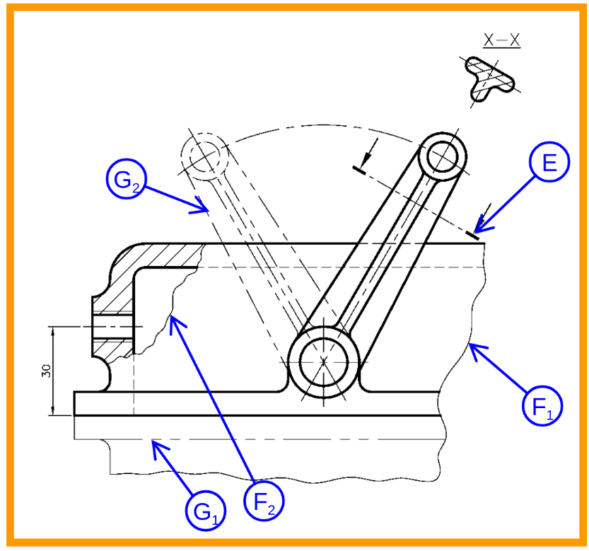
| G | Thin chain short double dashes | Outlines of adjacent parts. Alternative and extreme positions of movable parts. Initial outlines prior to forming. |
Precedence of Line
Visible line > Hidden line > Center line
-
Hidden line - Thin short dashes
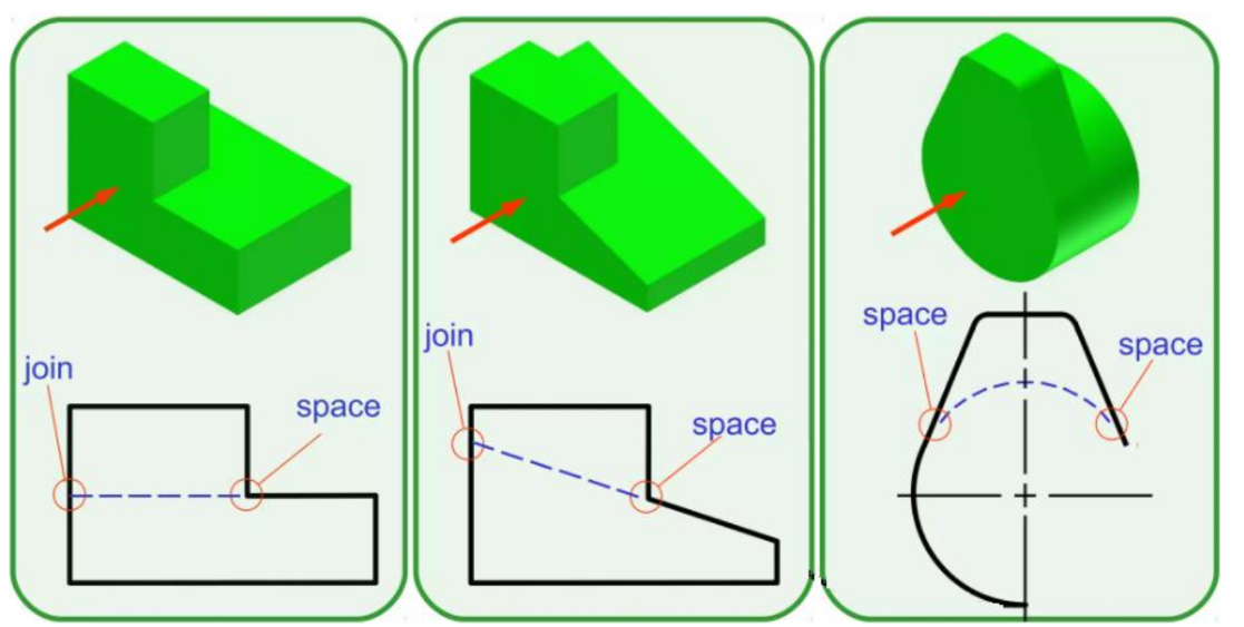
Intersections of hidden lines should form L, T, V or Y corners
-
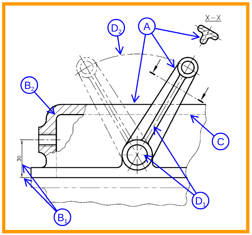
Centre lines - for symmetrical axis, bolt circles and path of motion
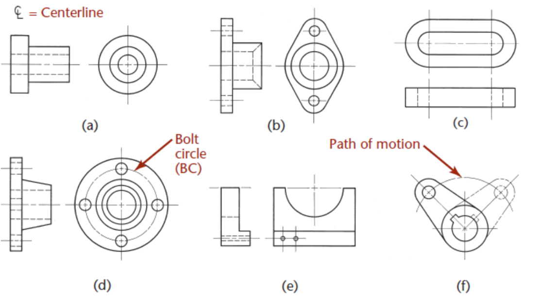
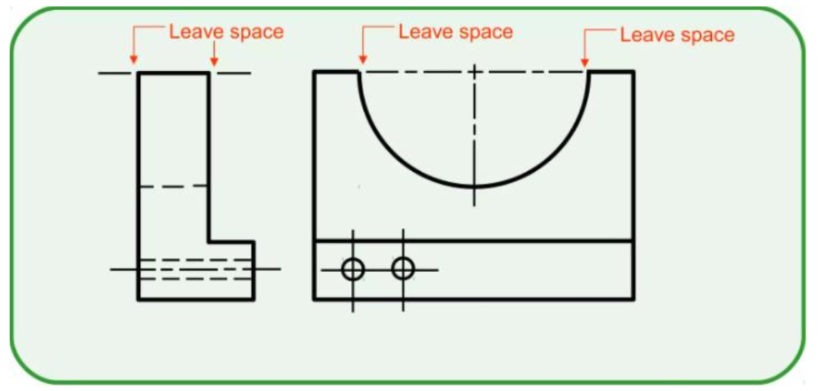
can be thin continuous line for small hole
Orthographic Systems
-
First angle Projection
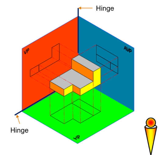
-
Third angle Projection
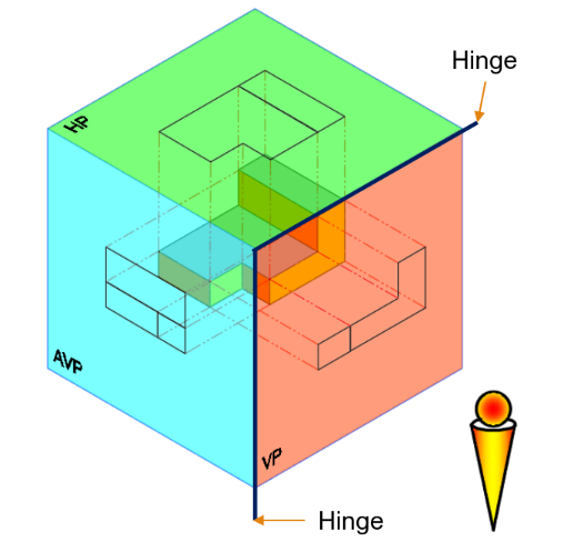
-
ISO Projection Symbols
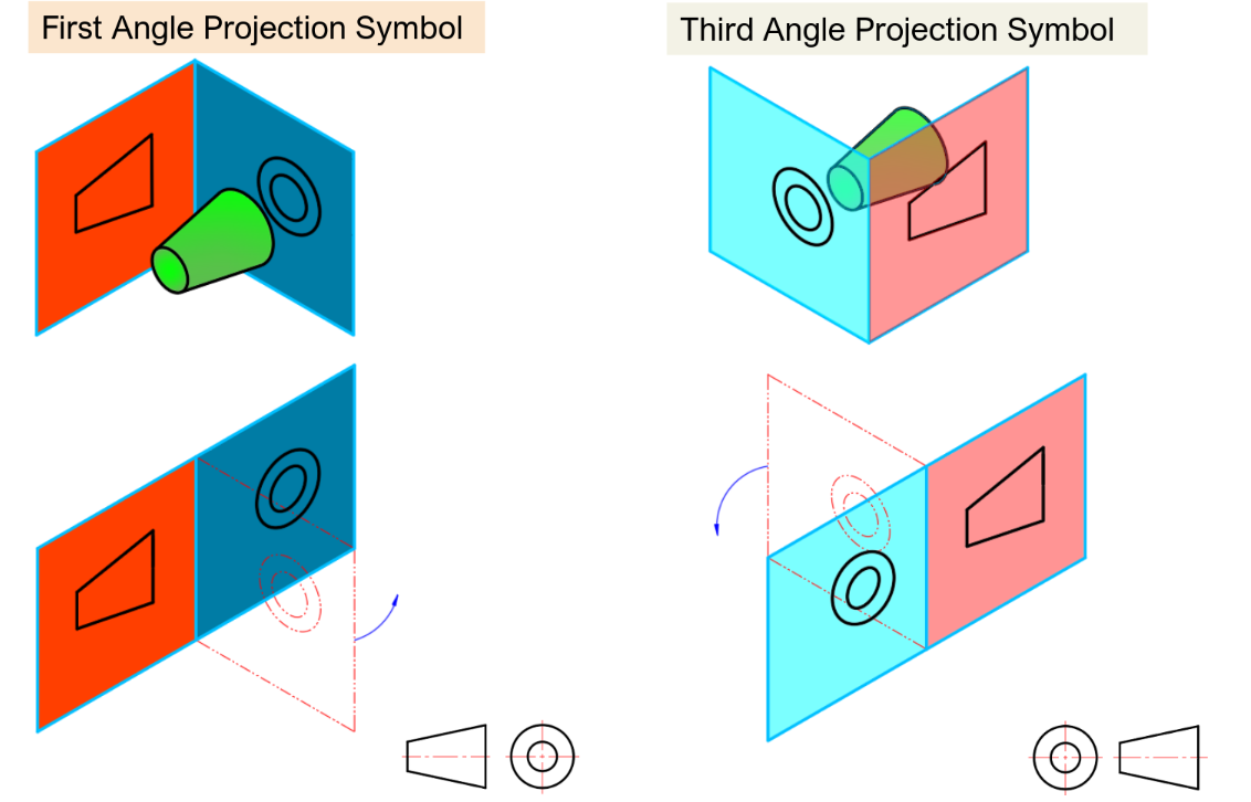
First angle is projected past the sight-line while third angle is projected back towards the sight-line
Isometric Drawing
Isometric — all angles are equal (30to horizontal) True-length distances are shown along isometric lines Hidden lines should be omitted unless absolutely necessary to completely describe the object
Visualising Orthographic Views
A straight, visible or hidden line means:
- Edge between two surfaces
- Edge view of a surface
- Limiting element of a curved surface
Normal surface
Parallel to plane of projection
-
True shape is projected onto that plane
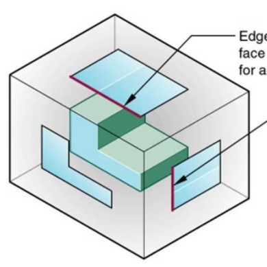
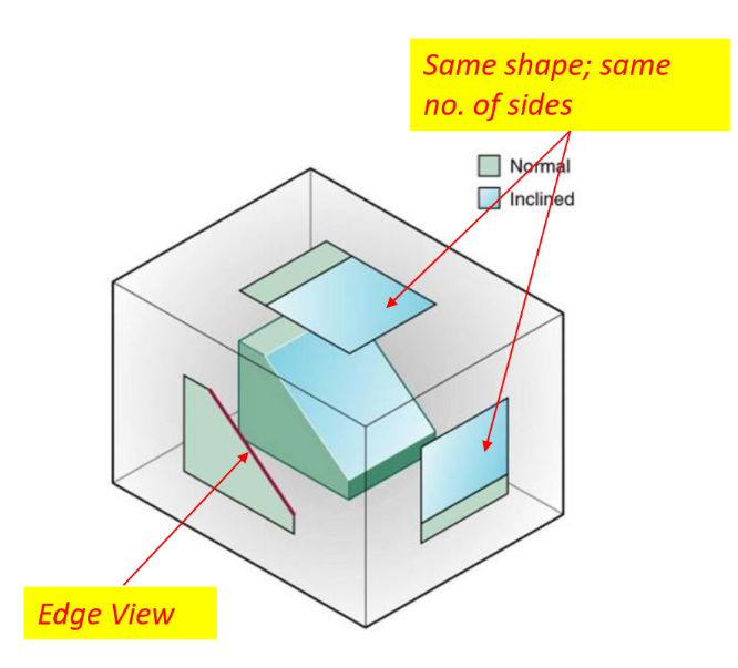
Inclined surface
Perpendicular to one plane of projection but inclined to adjacent planes
-
Edge view - True length on perpendicular plane
-
Same shape; same no. of sides on adjacent planes
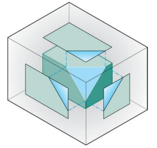
Oblique surface
Inclined to all principle planes
-
does not appear true size in any standard view
-
Parallel edges on the object appear parallel on all views
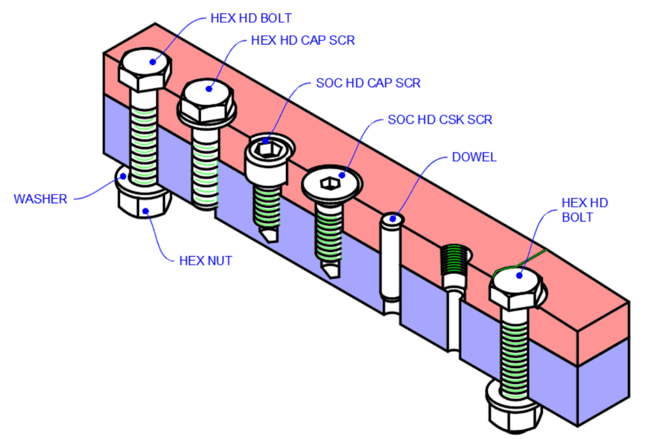
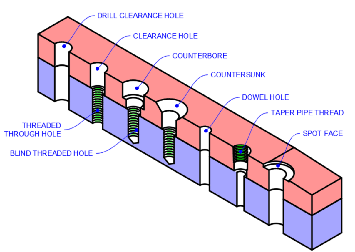
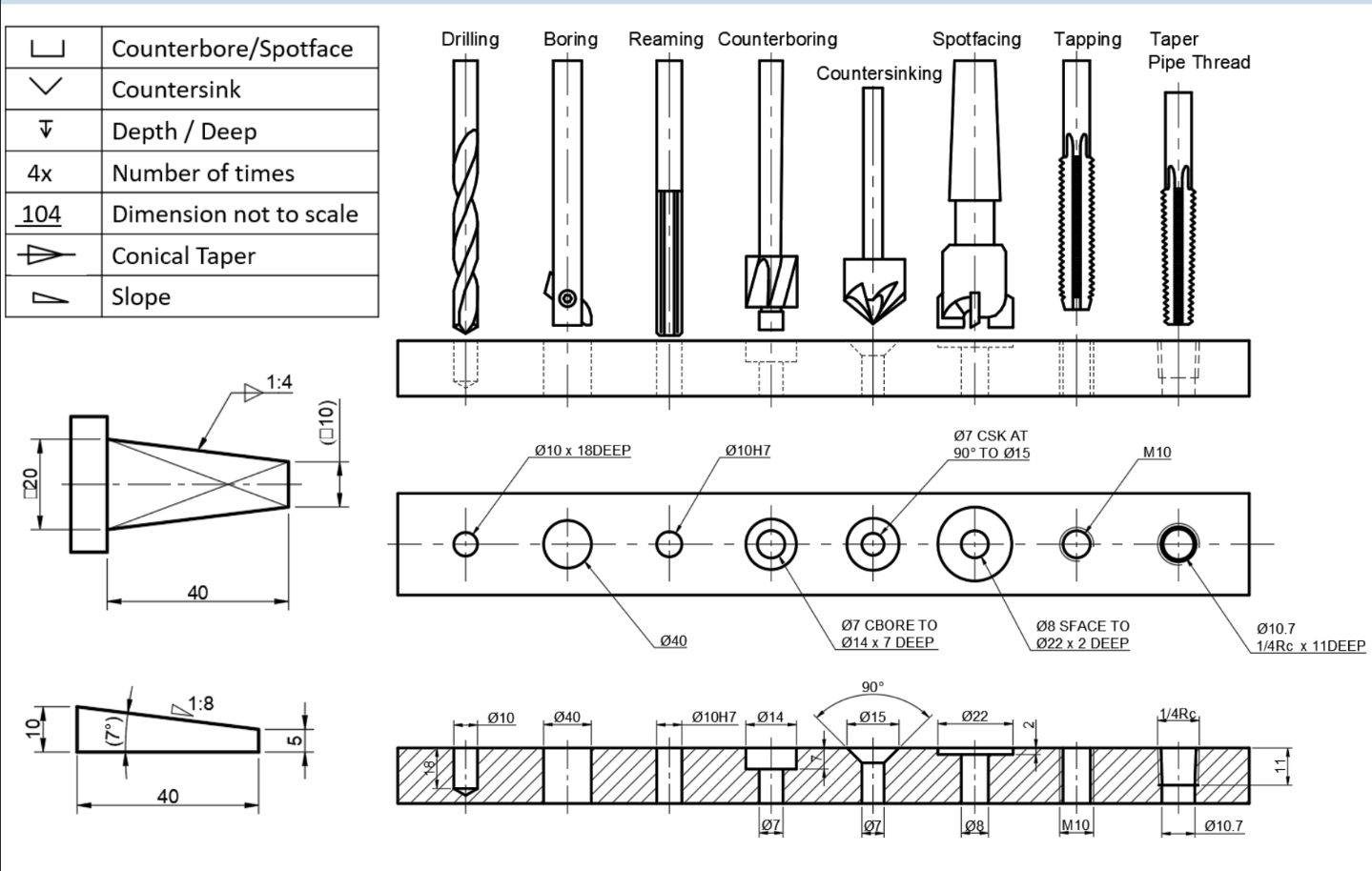
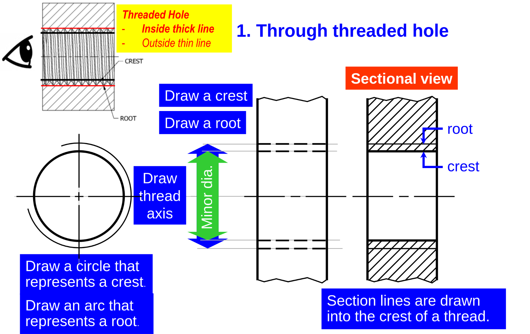
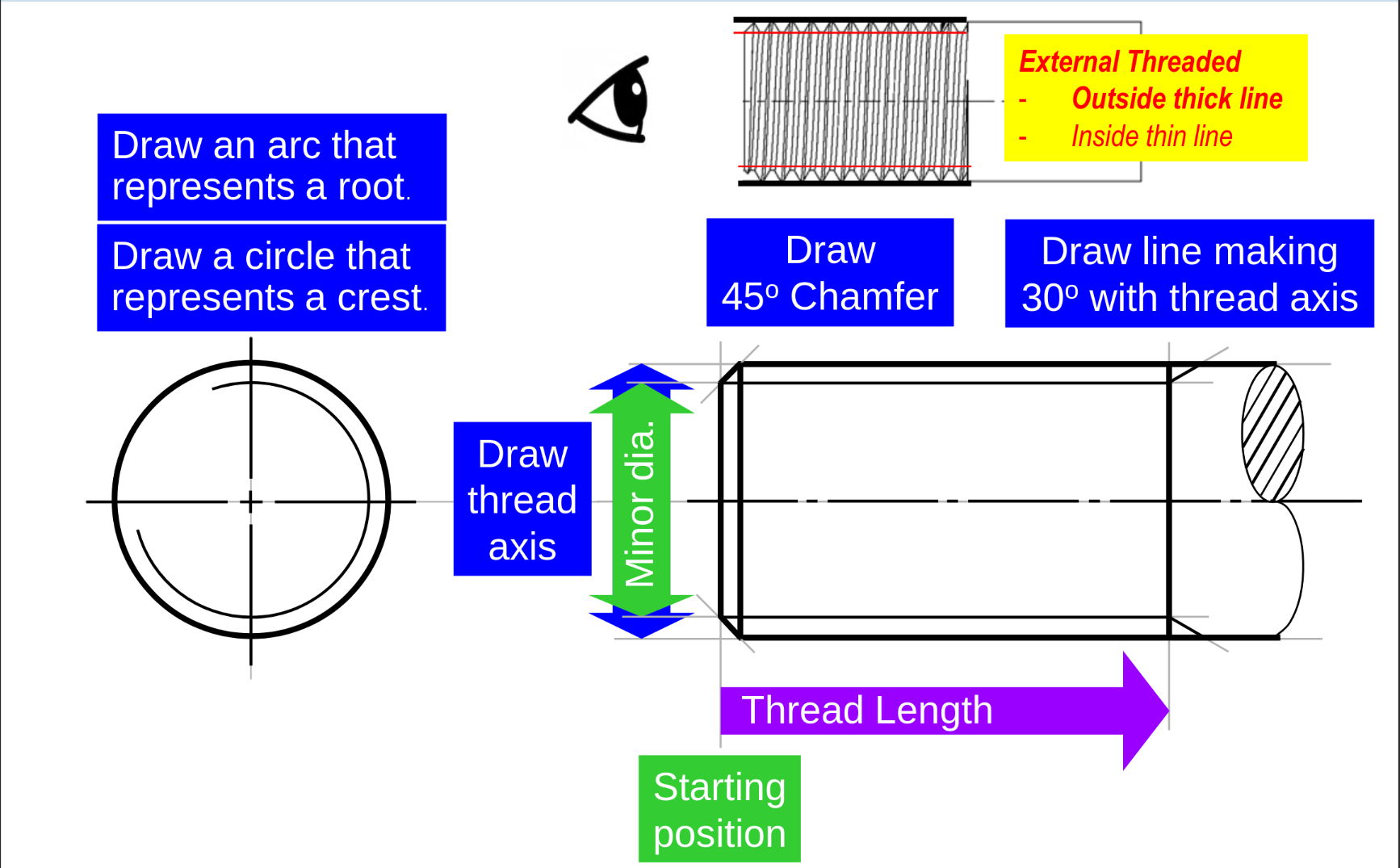
Holes & Threads
-
Threaded hole drawing
-
External thread drawing
Sectioning
To show internal features clearly, minimising hidden lines
Full Sectioning
Features
-
Features shown — behind cutting plan
-
No hidden lines
-
No need to section parts with no interior details (e.g. Shaft, screws, bolts)
- Particularly ribs and lugs — unless transversely cut Hatching
-
Hatched area should be completely bounded by outline
-
Same part — hatch in same direction & spacing
-
Hatching should not be parallel to outline
-
Thin parts can be completely black — gaps between thin parts needed for clarity Special cases
-
Lugs
-
Ribs
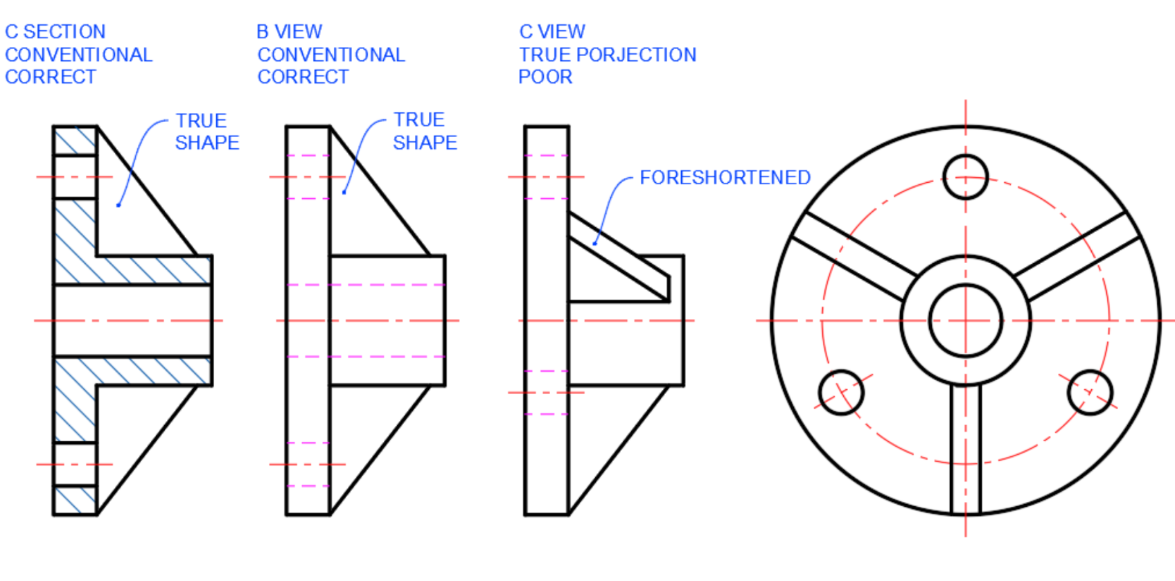
-
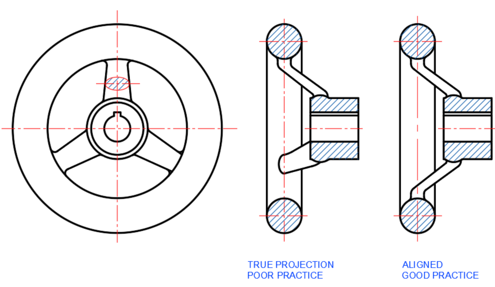
Spoke
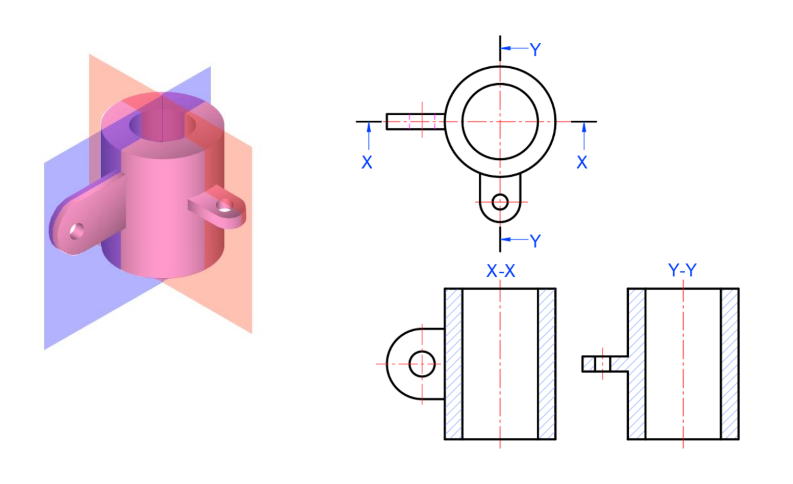
Offset Section
To show internal details that lie on more than 1 parallel plane
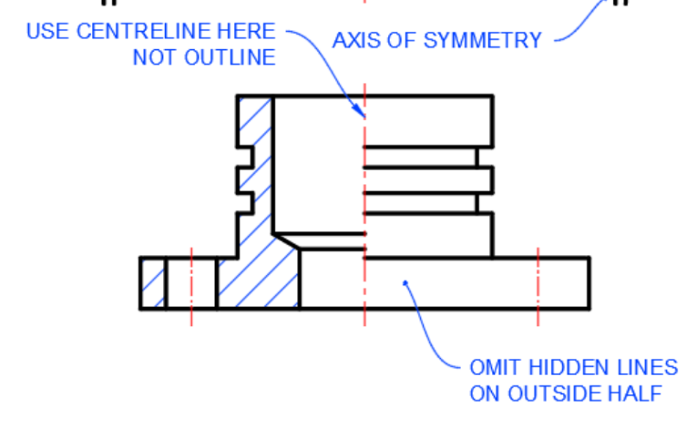
Half Section
-
Center line seperates sectioned half from unsectioned half
-
Hidden line is omitted in unsectioned half
Aligned section
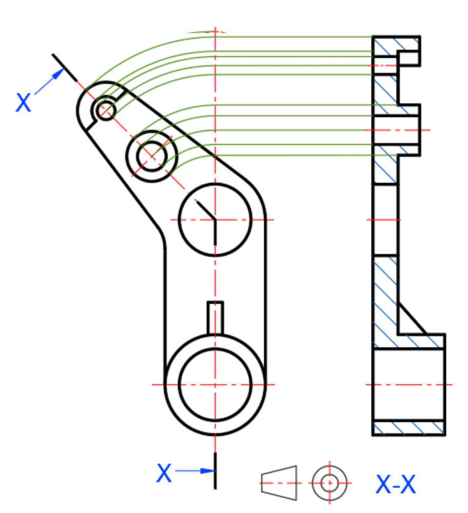
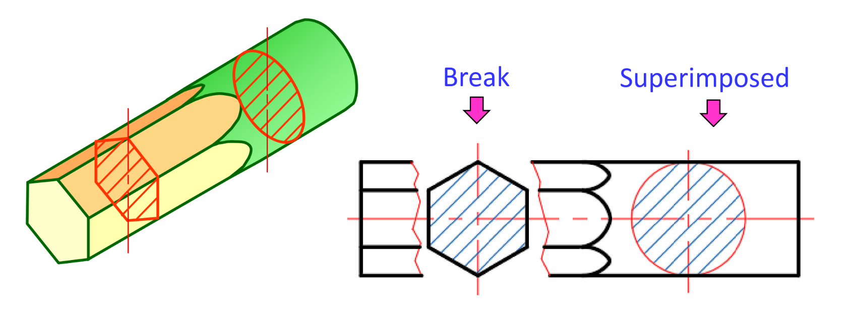
Revolved section
True length
By Aux view
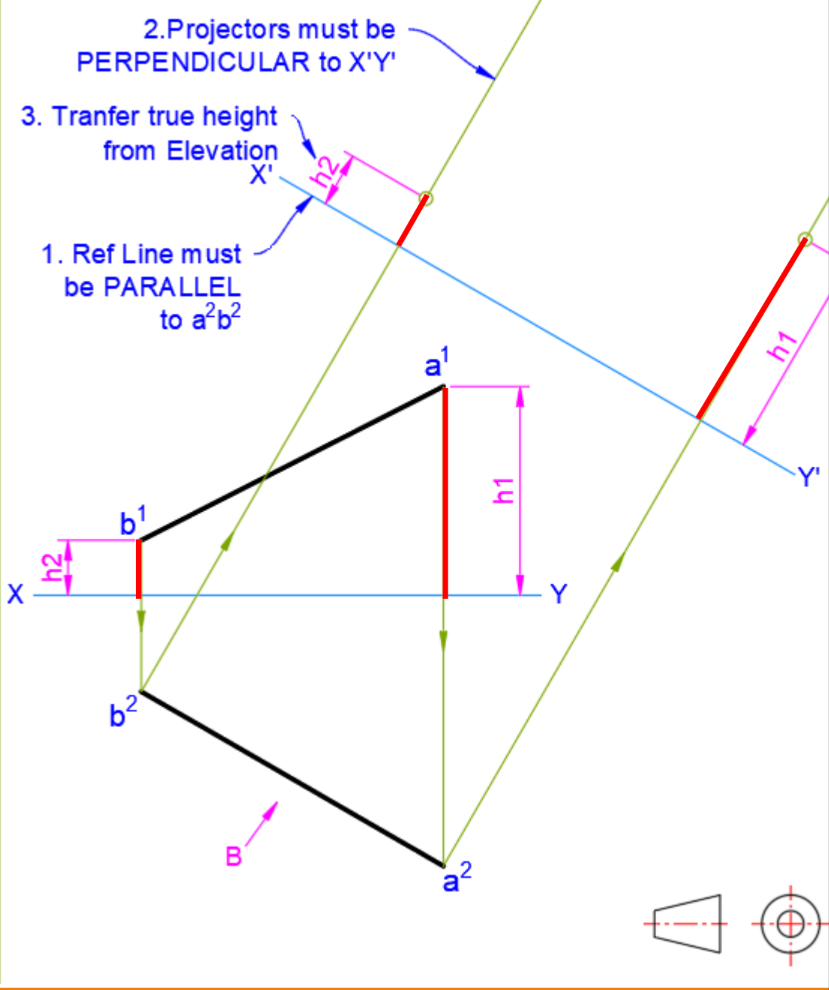
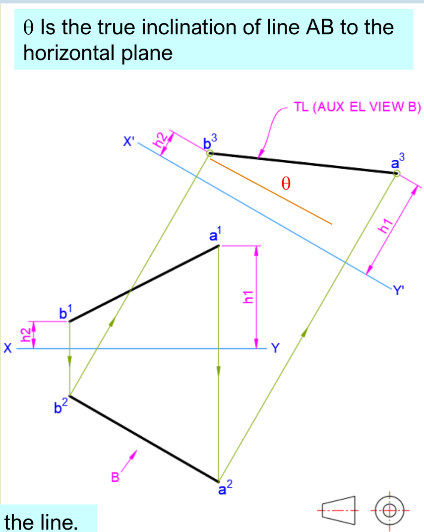
Identifying TL
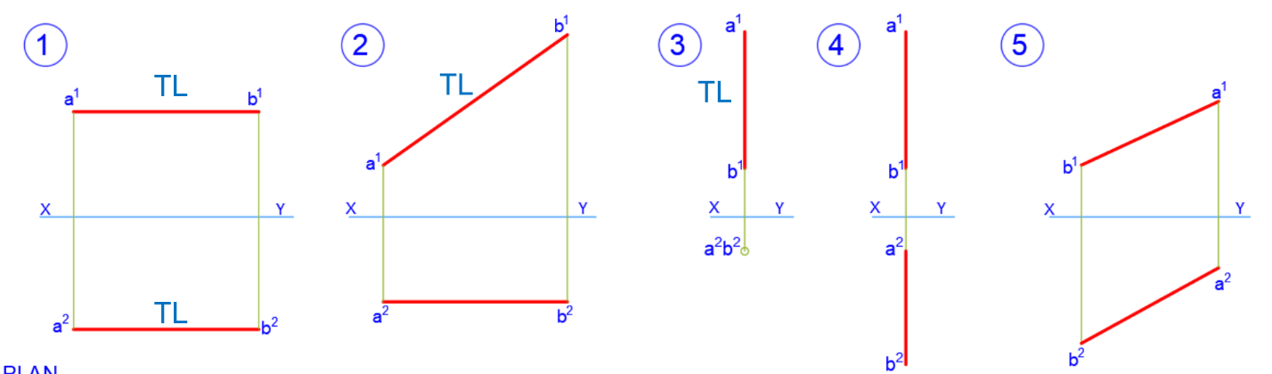
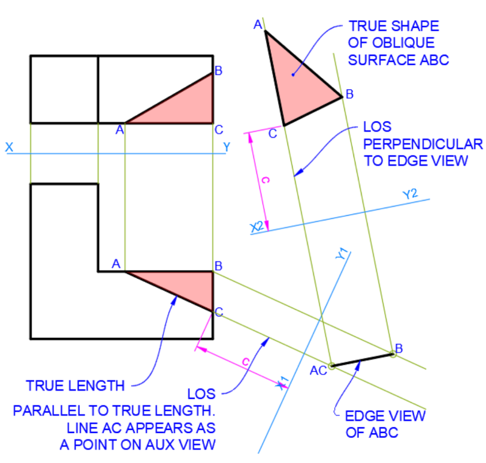
Finding True Shape
- Identify line with True Length
- Aux view perpendicularly to that line to find edge view (where plane is seen as a line)
- Aux view parallel to edge view to find true shape
Others
Dihedral Angle: Angle between two planes
- Angle between edge views Shortest distance
- Length between point(view) and line True angle
Auxiliary Projection
First vs Third angle
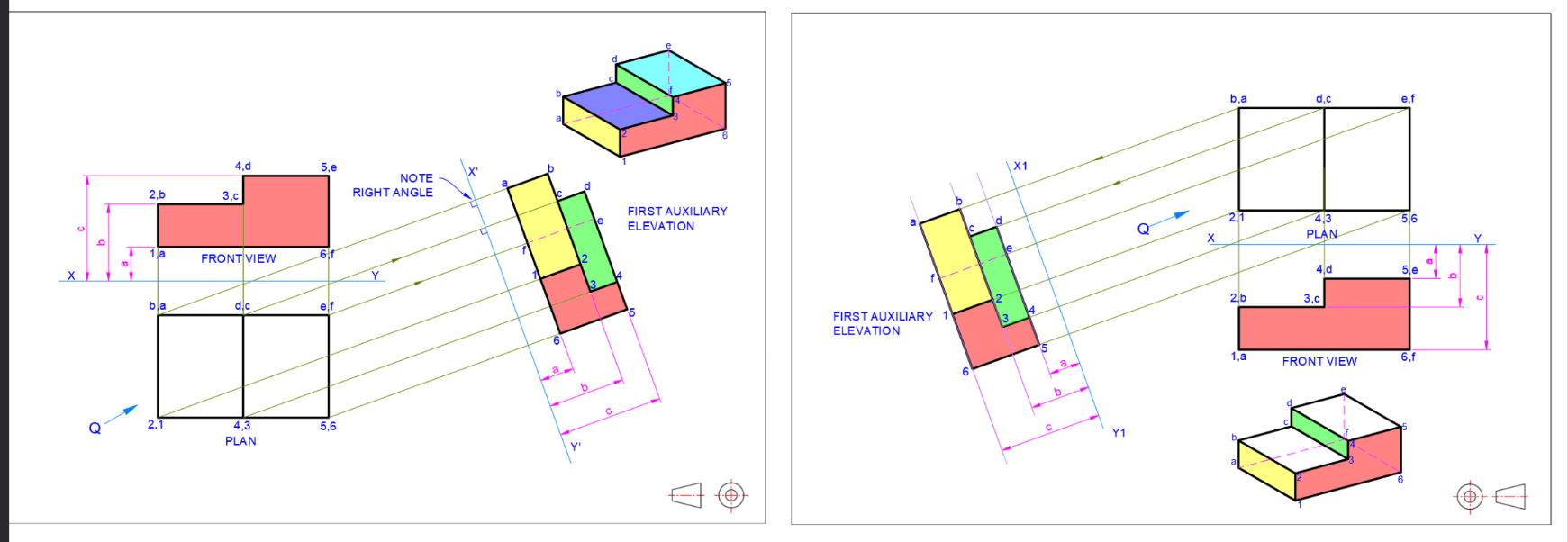 Views are the same, only relative position is changed
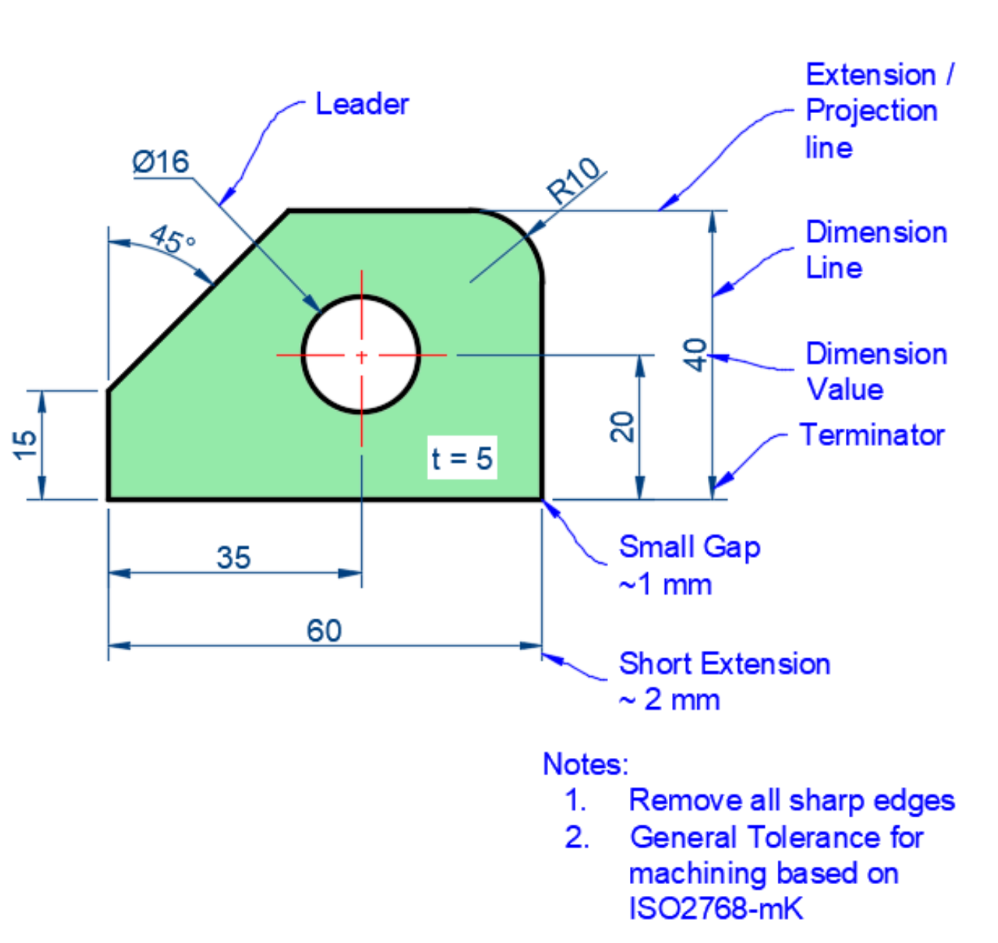
Dimensioning & Annotations
ISO R129 (Dimensioning) & ASME Y14.5 (GD&T)
Basic Information
Size & location of features — Material — Number required
Higher level Information
Tolerances (size and geometric) — Surface roughness — Assembly process description
Dimensioning practices
-
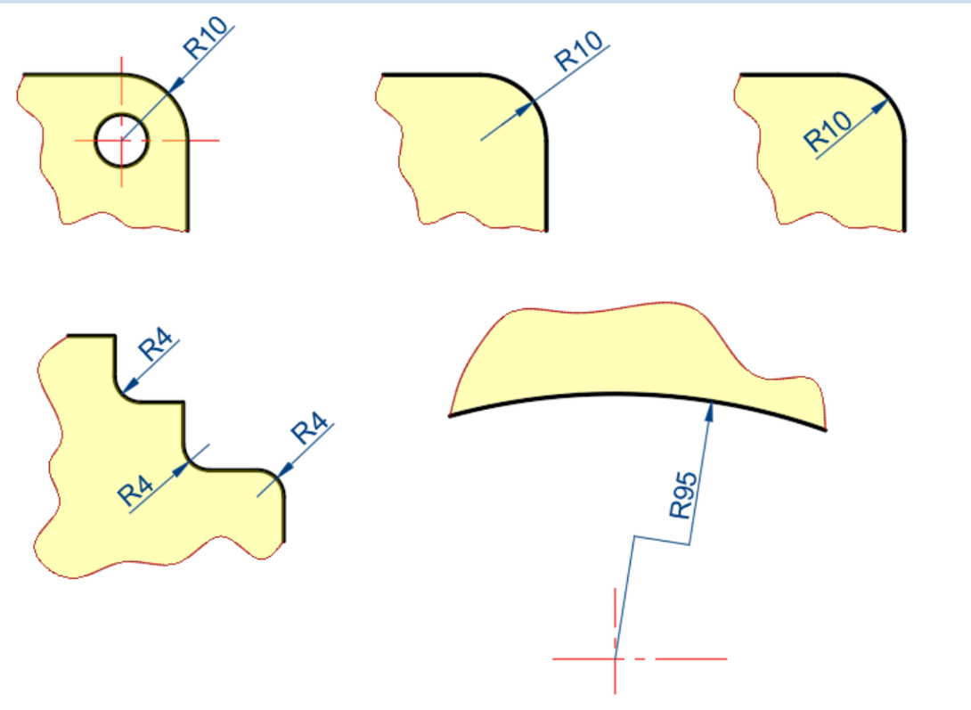
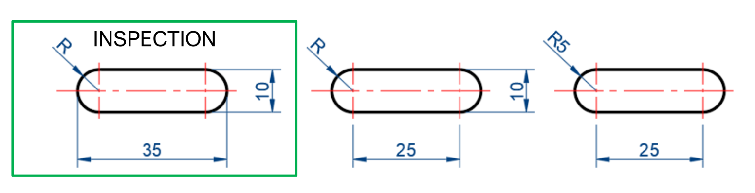
Radius
-
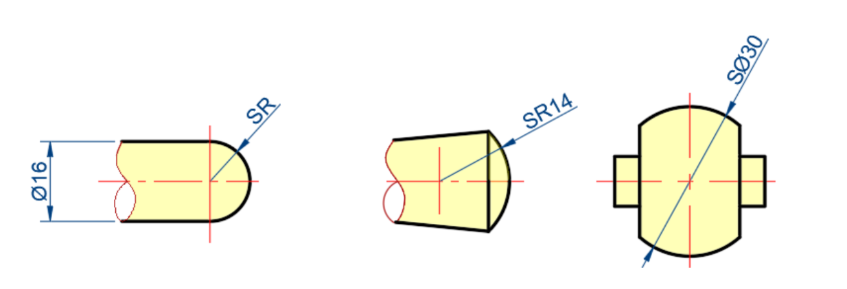
Spheric
-
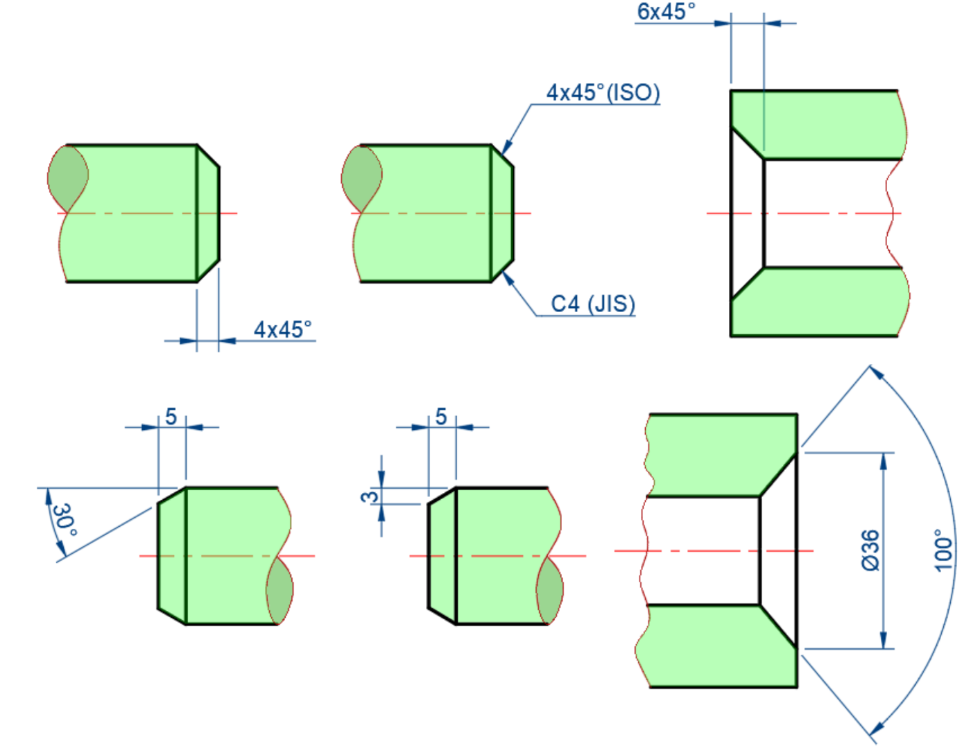
Chamfer
-
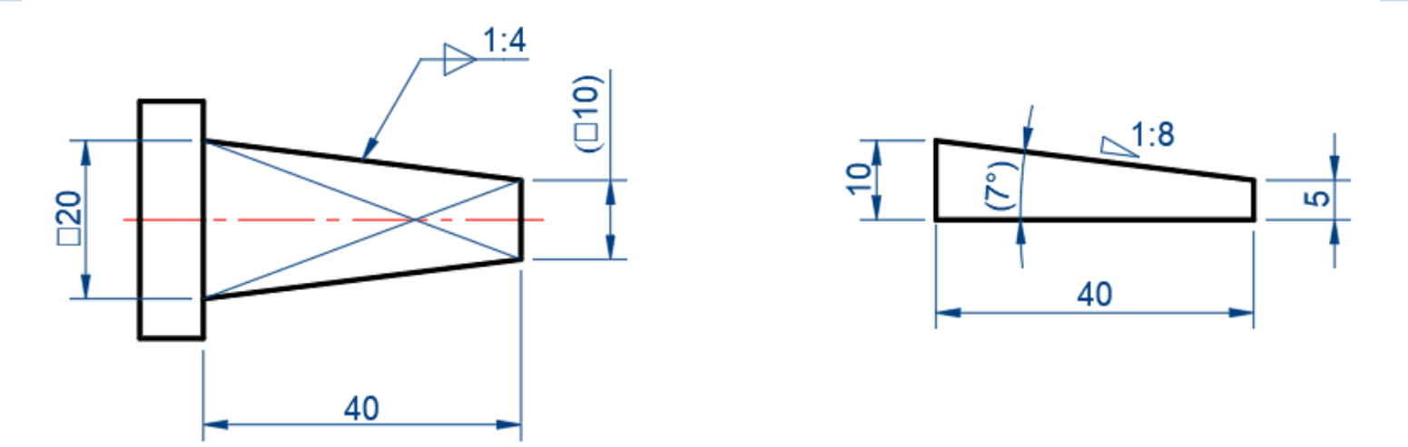
Taper / slope
-
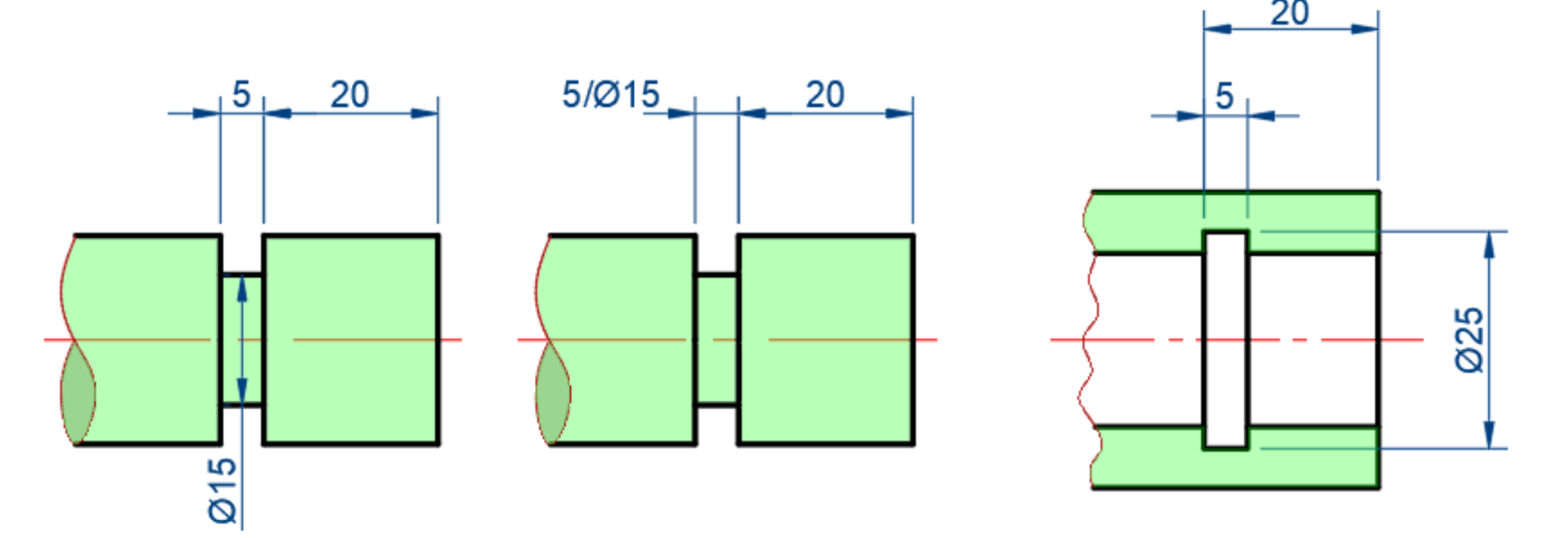
Keyway
-
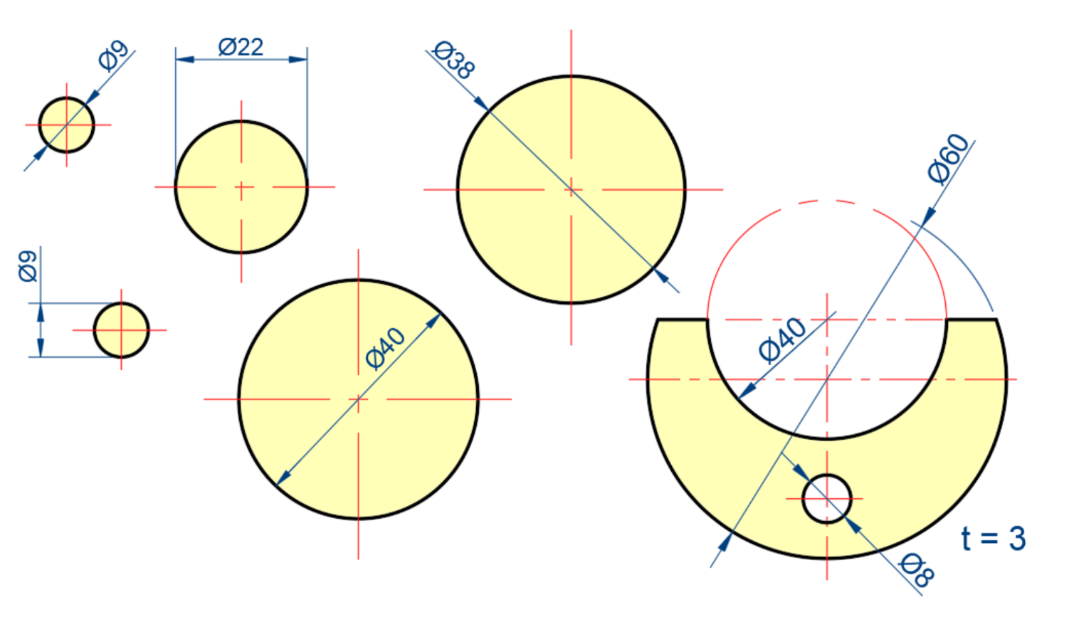
Diameter
-
Arc / Chord

-
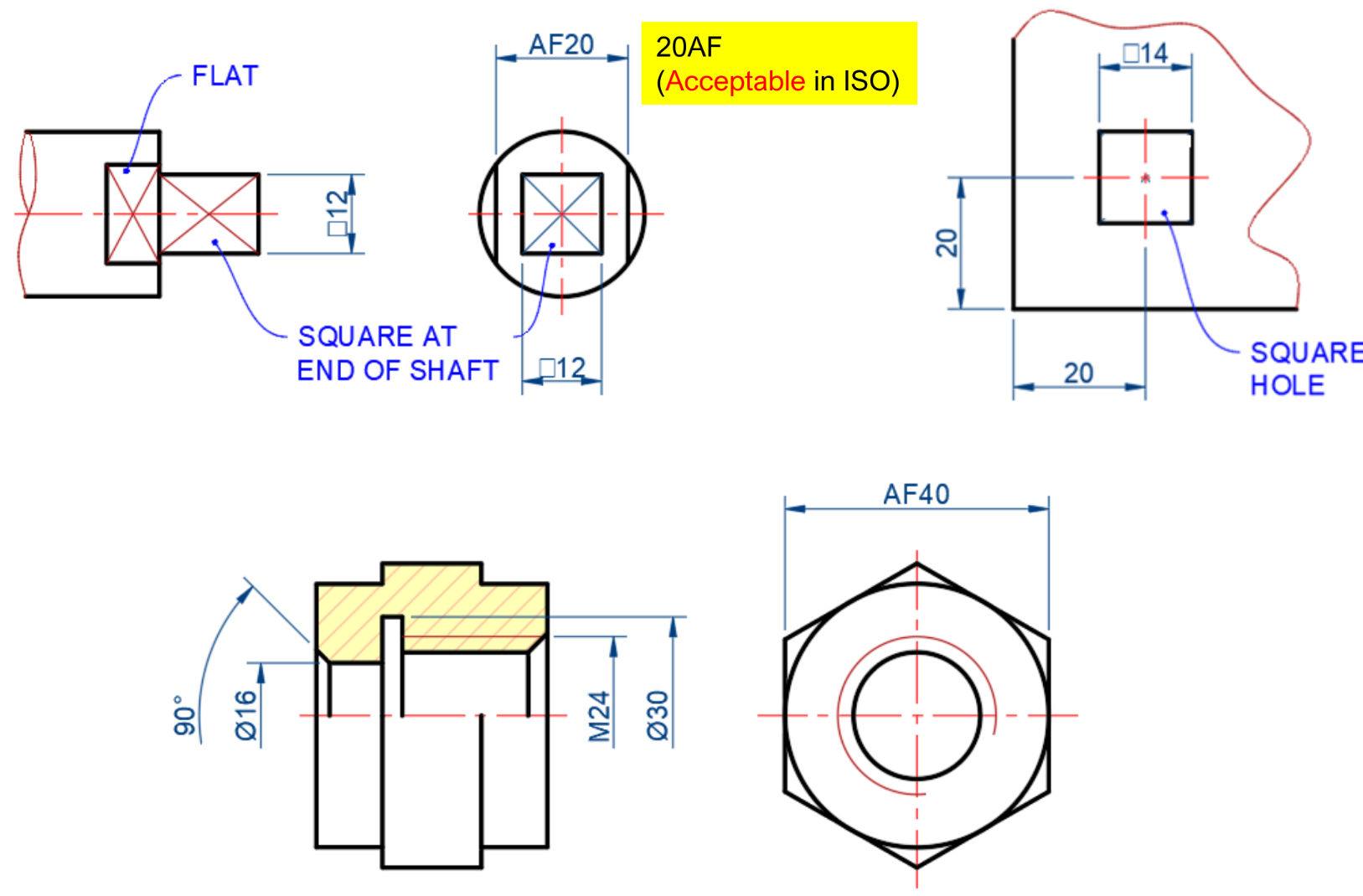
Square / flat
-
Undercut
-
Equally spaced repeated
Dimensioning practices (ISO R129)
- R for arcs (<180) — for circles (>180) — SR/ for spherical radius / diameter
- Don’t dimension hidden lines — pick views that show it’s true size and shape
- Dimension on views that show the contour
- Ensure all dimensions are accounted for — avoid over/under dimensioning
- Only angles have units
- Reference dimensions require parenthesis (xx)
- Locate circular features by dimensioning to centerline
- Use centerline for symmetry
- Dimension circles on side view > front view for clarity
Dimensioning appearance (ISO R129)
- Value should be written above dimension line — with offset
- Put values/arrows outside extension line if not enough space
- Dimensions should be outside the view — unless it improves clarity
- Extension lines should have a visible gap from view and extend beyond dimension line
- Extension and Dimension lines should not cross
- Extension lines can cross
- Line up dimension lines as much as possible
- Extension lines & notes should be drawn nearest to point of interest